Step 4 - Wiring
Time required
30 min for the wiring, optinally 2-3 hrs printing (Mark2 board option), 30 min wire assembly (if you do it on your own)
Preparations
Please follow the standard safety measures for working with electronic devices. We also strongly suggest to dip into the official extrusion upgrade documentation - online with videos / PDF, which comprehensively explains most of the required steps.
Obviously, you have to remove the cover from the electronics and unscrew the board in order to access the upper side. Depending on the position of your second feeder, you have to find a way for the wire harness to the underside of the printer.
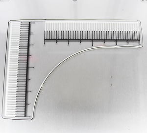
Overview
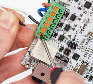
We have to connect the stepper and these four cables to the board.
From left to right:
- temp sensor -> Connector marked Temp 2
- heater -> the two wire terminals in the center
- hotend fan -> we use a Y-cable to connect both heads to the connector already occupied by head 1
- part cooling fan -> we use a Y-cable to connect both heads to the connector already occupied by head 1
Option A - Using cable extensions and Y-cables
Cable lengths
Most likely the standard wire harness will be too short for a clean installation. So besides the required Y-cables we also extend the other ones.
Heater, temp sensor, stepper
This is the easy part. The UM2 board has connectors for these already installed.
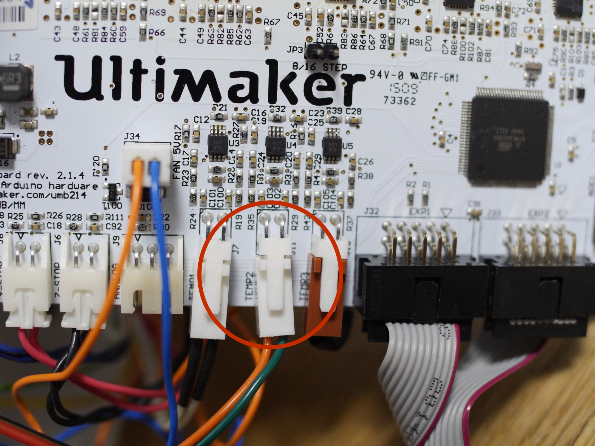
Connect the extension cables to the cables coming from the print head / stepper. Connect the extended stepper, temp sensor and heater cables to the board. The connectors are marked "E2", "TEMP2", "HEATER2".
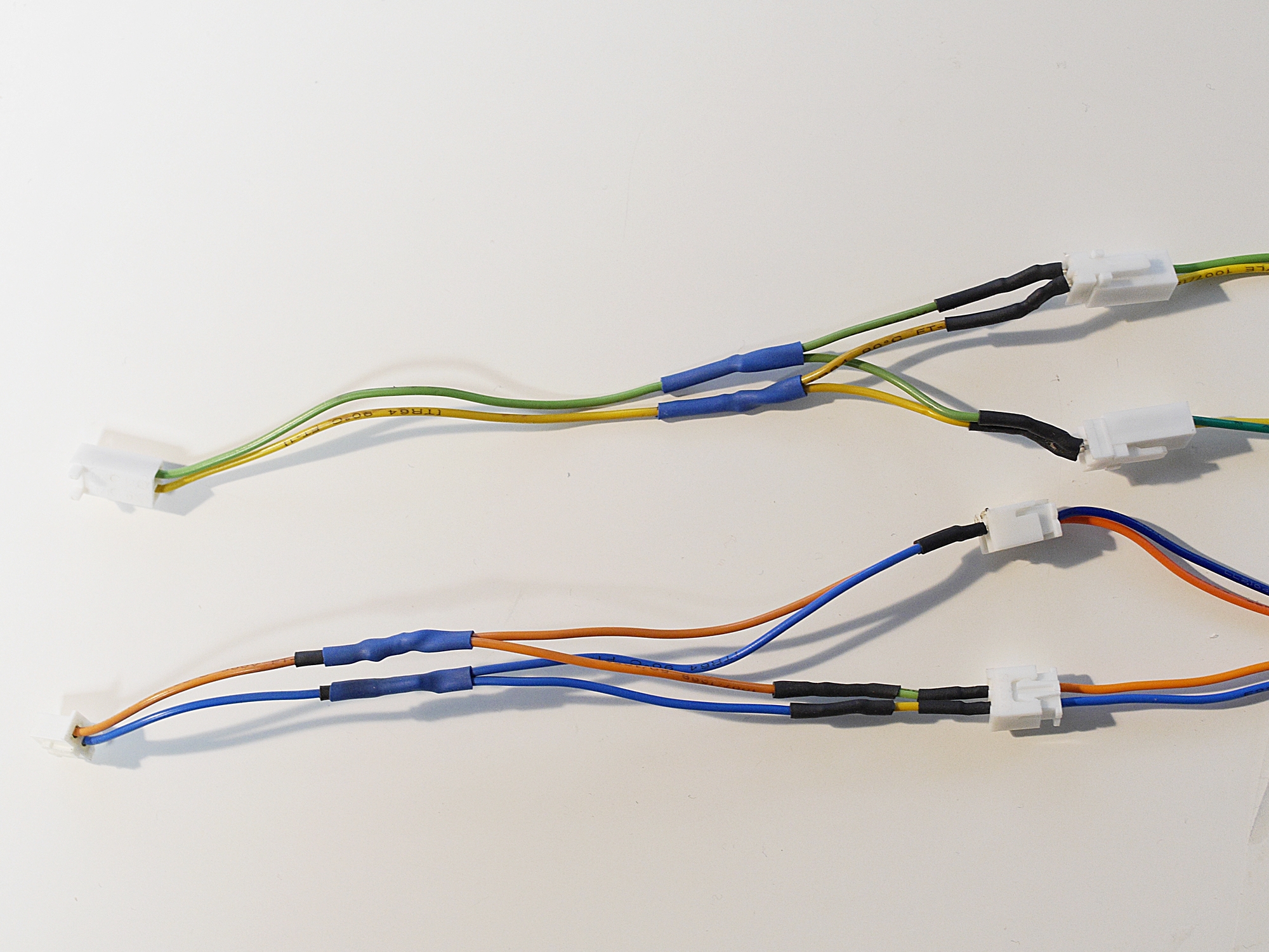
The fans - part cooling and hotend
We will connect them in parallel to the ones already there. But there's only one set of connectors. We have to use Y-cables to connect the devices of both heads to one board output. The on-board MOSFET drivers are strong enough to supply the fans of both heads simultaneously.
Unplug the part cooling and hotend cooling cables from the board. The connectors are marked "FAN PWM" (next to the on/off switch) and "FAN 5V" (next to the "Ultimaker logo").
Connect these two cables and the repspective ones from the other head to the Y-cable's double end.
Connect the single ends to the board.
Finishing
Re-install the board. Reroute the cables in a bend next to the Z-motor to ensure they'll fit the hole in the cover. Install the cover and make sure nothing is jammed.
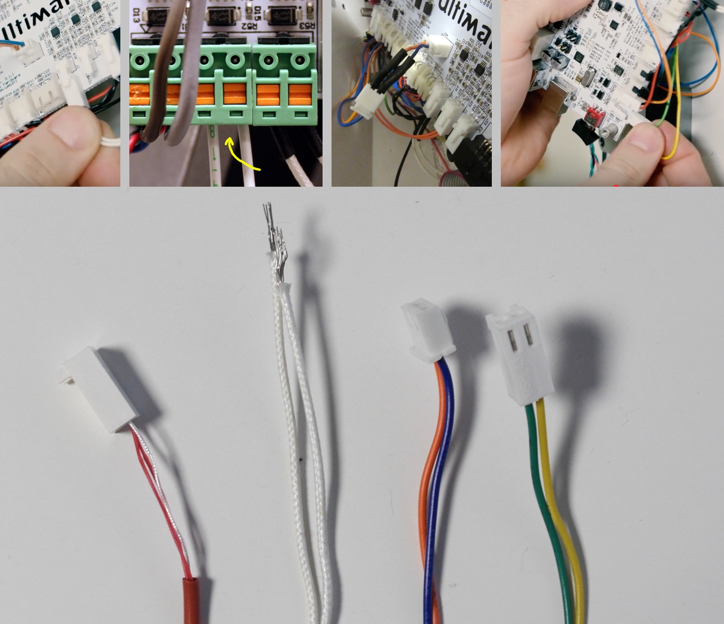
Making the y-cables
Watch Neotko sugarpop's how-to video to get an idea what you have to do. Part cooling and the hotend fan use different connectors, so you have to prepare one with Molex connectors and one with JST-XH connectors.
Part cooling fans: one Molex KK 22/01/2025 -- connecting to -- two Molex 22-23-2021, wire: 26 AWG, 200 mm
Hotend cooling fans: one JST XHP-2 -- connecting to -- two JST B2B-XH-A, wire: 26 AWG, 200 mm
Option B - Using the Mark2 extension board
The elegant way. With the extension board you will be able to control the additional part cooling fans separately and you can connect much stronger fans. Find below the perfect installation guide by the board's originator, UM community member SyntaxTerror:
Step 1: Interfacing with the controller board.
There are two ribbon cables connecting the main board to the controller board. These cables carry several previously unused signals which we're taking the liberty of exploiting (we're getting them there rather than on the main board in order to create the least interference with other mods people may have installed).
First thing's first, remove the cover from the controller. This is somewhat more involved than it might seem, in case you've not tried it before. There are two tabs digging into the bottom plate of the printer, and they require a surprising amount of force to dislodge. Use a flat screwdriver to carefully lever it off the bottom plate. Further, the cover serves to stabilize the display from behind, so be very careful when removing it.
You'll be rewarded with this:
The EXT/EXP connector is our target. Connect the 6-way ribbon cable to the pin header on the board. The pin header has no keying/polarity protection so be careful not to turn it 180 degrees. I've tried to take precautions against this by using a locking ribbon cable header in my cable assembly, but I can't guarantee it won't slide on the wrong way... especially if you have very powerful fingers. 
In any case, the red wire designates pin 1 on the cable - when mounted it should look like so:
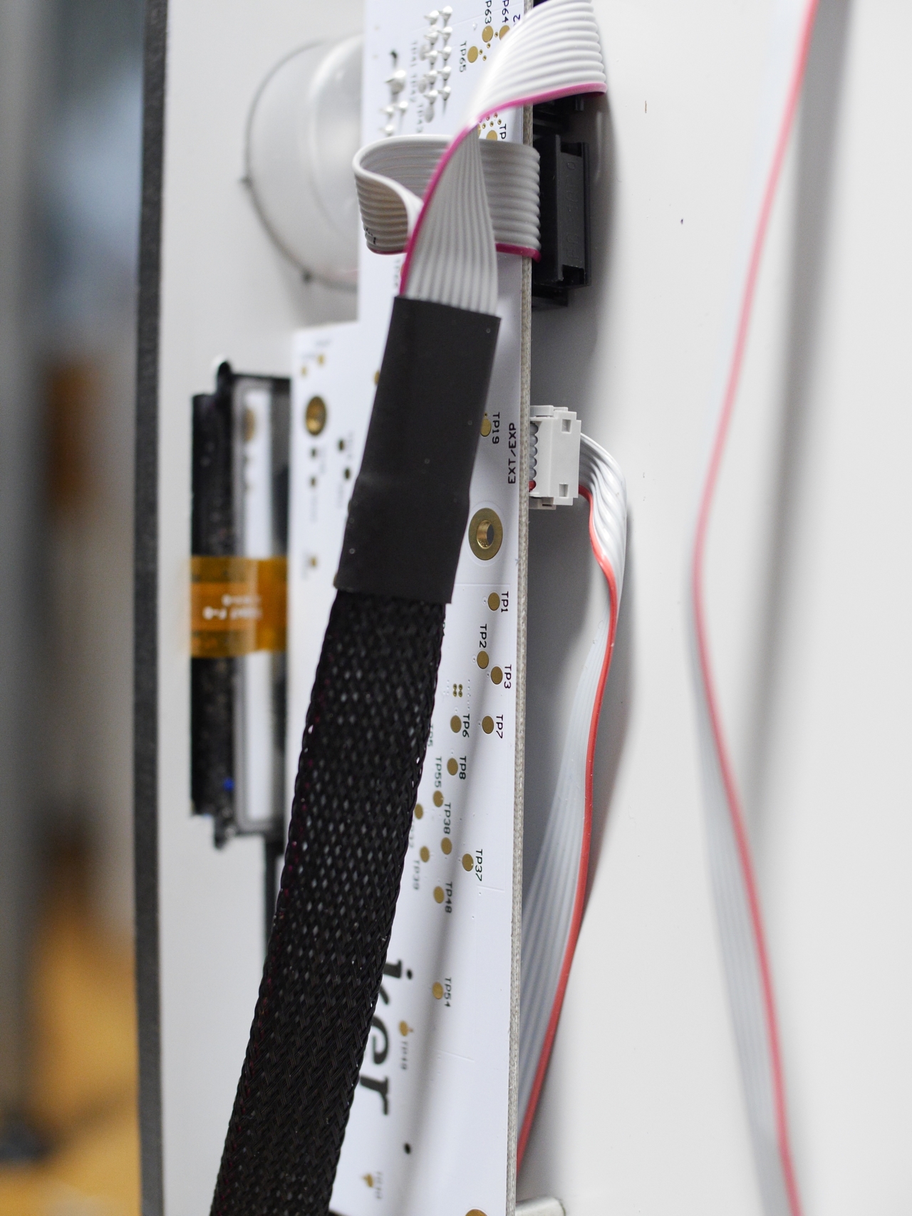
Now slide the other end of the cable underneath the controller board. This is to prevent pinching:
Reinstall the cover. Again, be careful. It's easy to forget the display in the effort to ensure the cables aren't getting molested by the edges of the cover when you press the cover tabs back in place. Again, a surprising amount of force is needed. The tabs we're talking about are these:
That concludes the trickiest part, I believe.
Step 2: Interfacing with the main board.
We need three things from the main board. 24 volts, heater output, and temperature sensor input. In order to access the 24 volt header it is necessary to remove the board from the bottom plate:
24 volt supply is taken from J19.
It's a 0.1" header, so there's no protection against reverse polarity here, at all. BE VERY CAREFUL to install this correctly. In fact if you mess it up the universe will implode, so don't do it. The board has +/- markings on it. As good practise, I'm making absolutely certain to use a black wire for ground on this cable assembly. Insert the header:

Next, use AWG 18 wire, preferably something insulated with teflon, for the heater connection.
Lastly, a Molex cable for the temperature sensor:
Reinstall the board on the bottom plate, making sure that all the newly installed cables approximately follow the heater cables.
Reroute the cables in a bend next to the Z-motor to ensure they'll fit the hole in the cover. The heater cables can be a bit stiff, since they are heavy gauge wiring.
Alright, that's the main board done.
Step 3: Installing the expansion board.
For the sake of this tutorial, I'm assuming the wire loom for your second print head enters the printer on the opposite side of the first head. You're of course free to modify as you see fit
You'll need the PCB carrier and cable clamps which are available here.
First off, use 4 M3 screws to mount the PCB carrier:
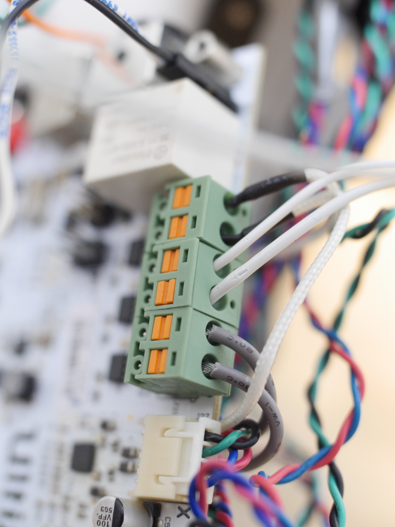
Connect the main board wiring:
Again, it is equally important to observe correct polarity of the power connector here! When in doubt, check the copper side of the board:
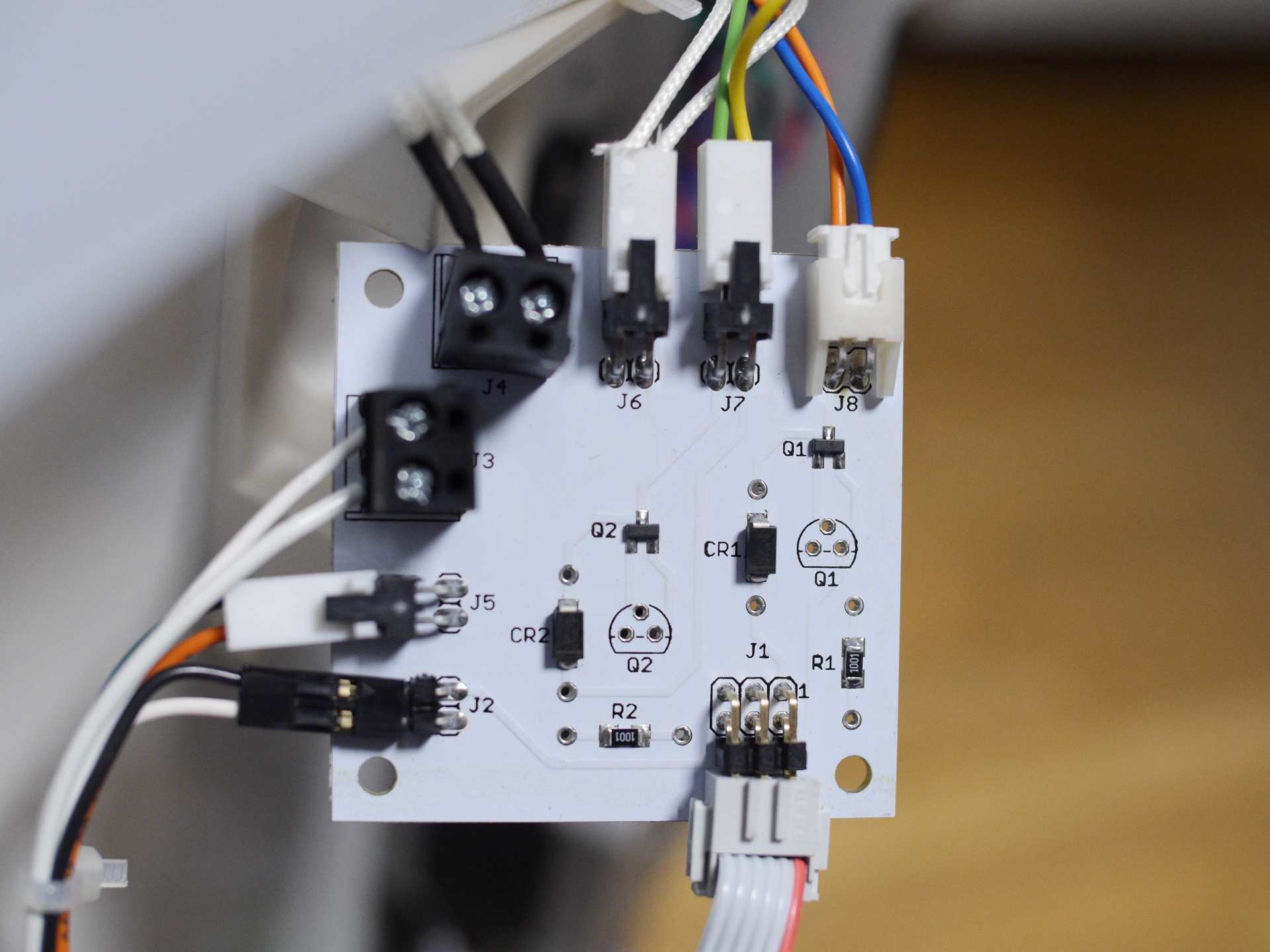
Now connect the print head to the expansion board. Note that it's possible to swap the connectors for the temperature sensor and the model fans. The model fans are the yellow/green wires.
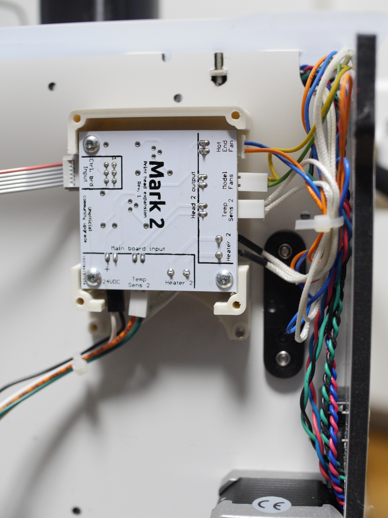
Install the expansion board in the PCB carrier and tidy up the wiring a bit. I cannot recommend strongly enough using a cable tie around the main board wires. This will prevent the non-locking 24 volt header from accidentally getting pulled out:
Using M3 screws and nuts, Install the cable clamps to secure the ribbon cable to the bottom of the printer:
Lastly, and this concludes the modification: Install the ribbon cable from the controller board. Again, make sure to observe polarity.
You should finally wind up with something that resembles this:
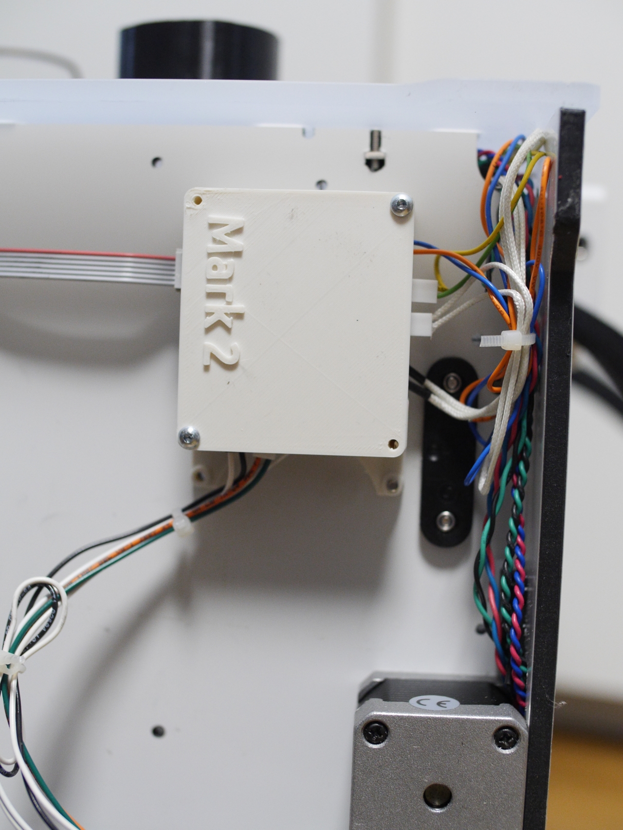
Aaaand we're done here