Step 2 - Head, coupling, dock
This is the Mark2 core part. It realizes the - so far unique - simple but precise kinematic coupling, which can be automatically attached and detached without using additional actuators.
Time required
6-10 hrs for printing, 30 min for assembling.
Options
This documentation covers the clamped dock, which uses two wedges to clamp the dock to the frame. If you feel unsafe with the clamping there's the tesa-stick-dock, which uses two-sided adhesive to attach the dock to the frame.
Download the stl files from Github, you need:
- coupling
- head-a
- head-b
- clamping-dock
Besides the printed part you need:
- the additional printhead (e.g. from the extrusion upgrade kit)
- 8 magnets, 6 mm diameter, 3 mm thickness, holding foce approx. 900 gr
- 3 M3x30mm screws
- 3 M3x16mm screws,
- 3 M3 nuts
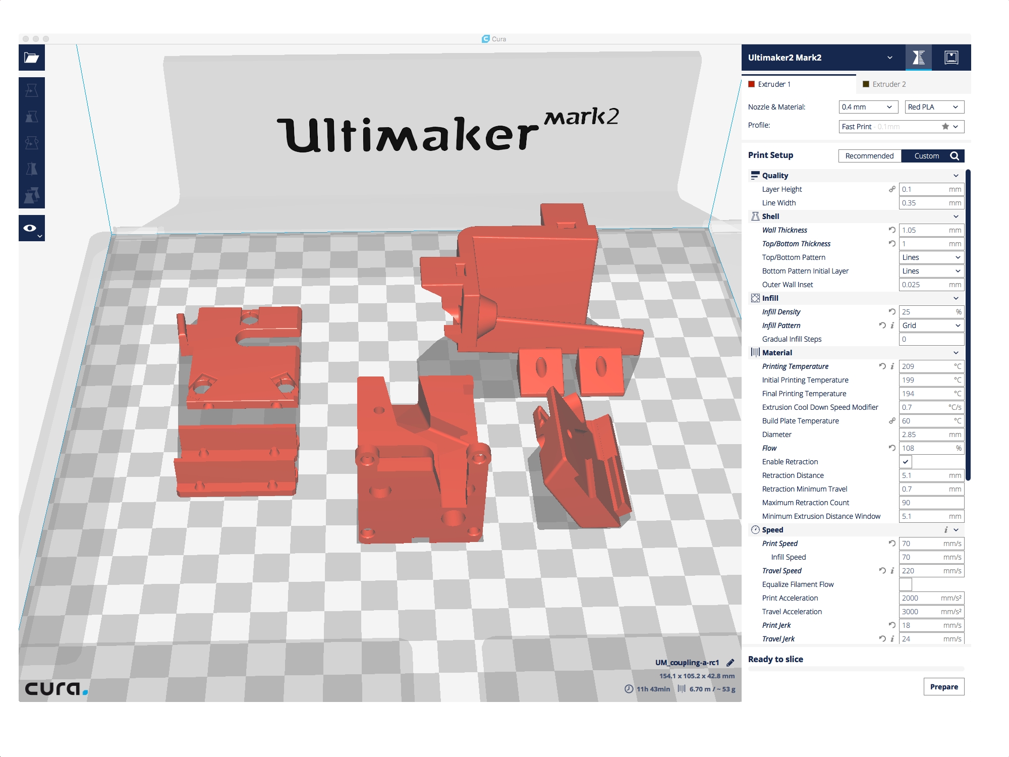
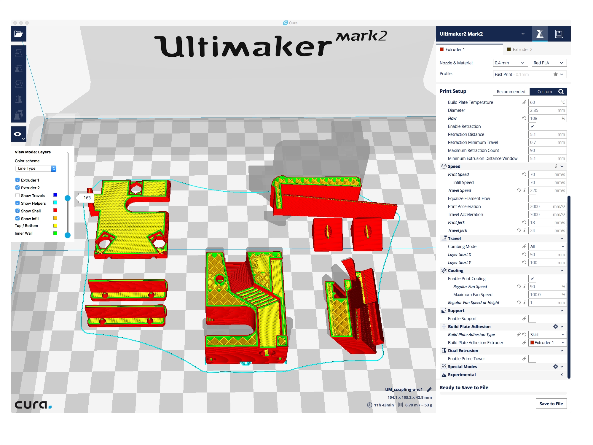
Import to your favourite slicer and arrange nicely.
Recommended print settings are:
- 0.1 mm layer height (important),
- 3 lines for the walls,
- bottom/top thickness 1 mm,
- infill 25%.
There's no support required, except "head-a". Turn on support for this part to get a decent bottom surface for the 3 holes for the magnets.
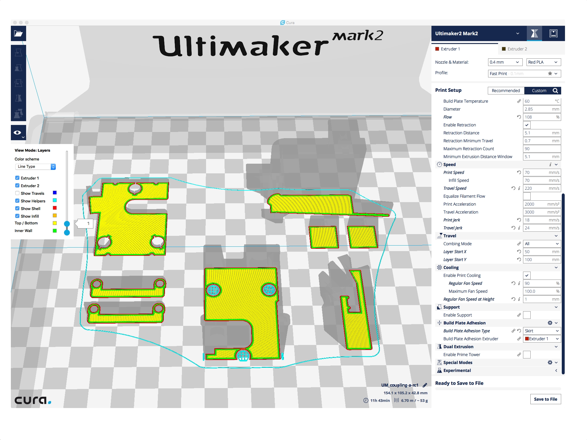
Brim shouldn't be necessary if the printbed is properly calibrated.
We recommend heat resistent material like high temp PLA (GreenTec, PlaTec) or something comparable.
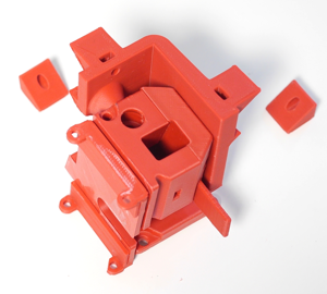
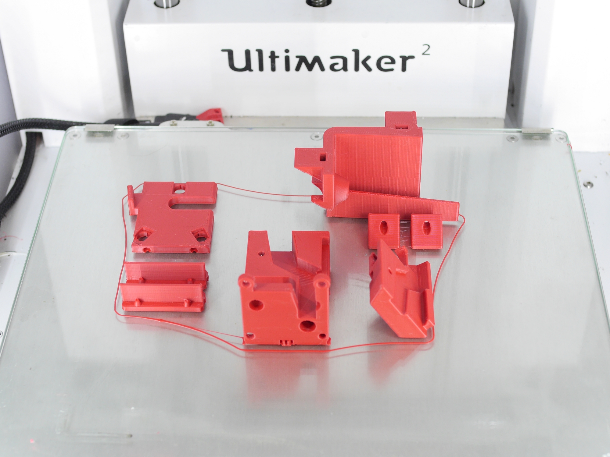
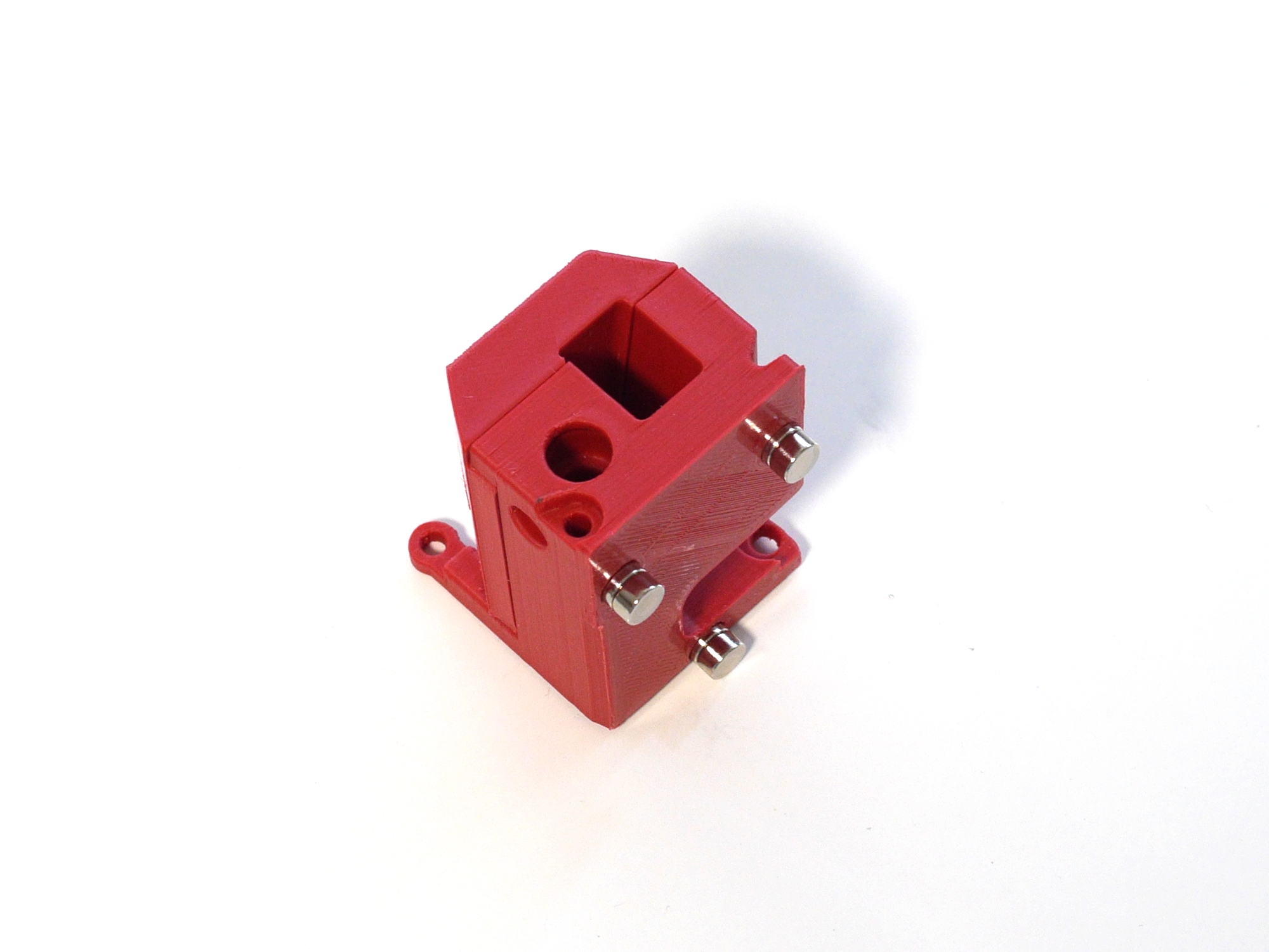
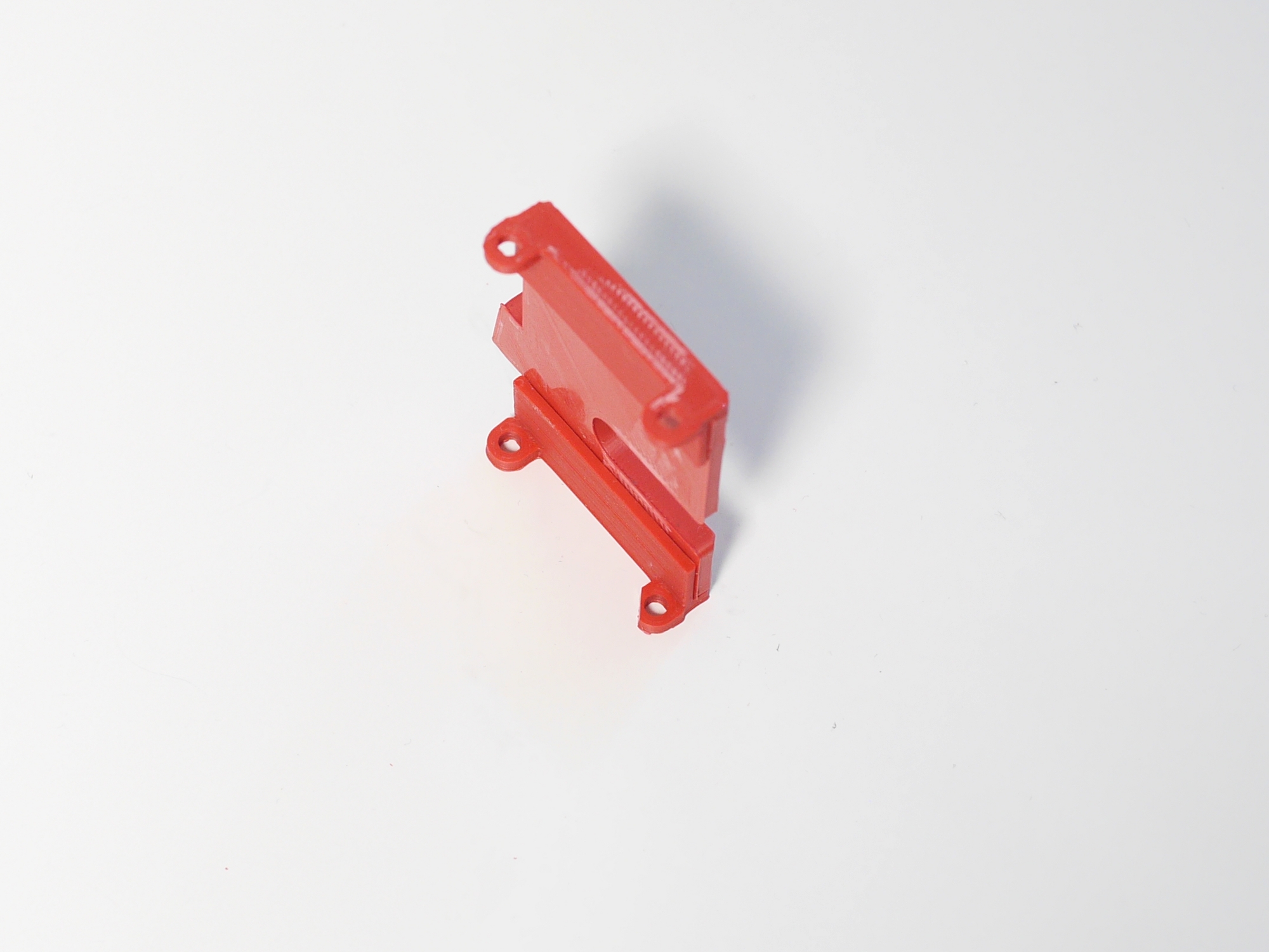
That's how it should look like.
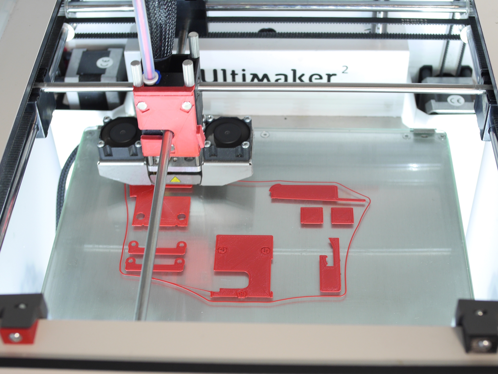
Printing will take 6-10 hrs, depending on speed settings.
Please note: It's a very good option to get the flex-wedge on Github and print two of them separately with some semiflex material. They provide even better clamping for the dock without any risk of overtightening.
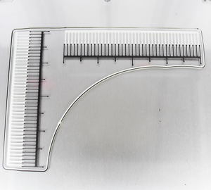
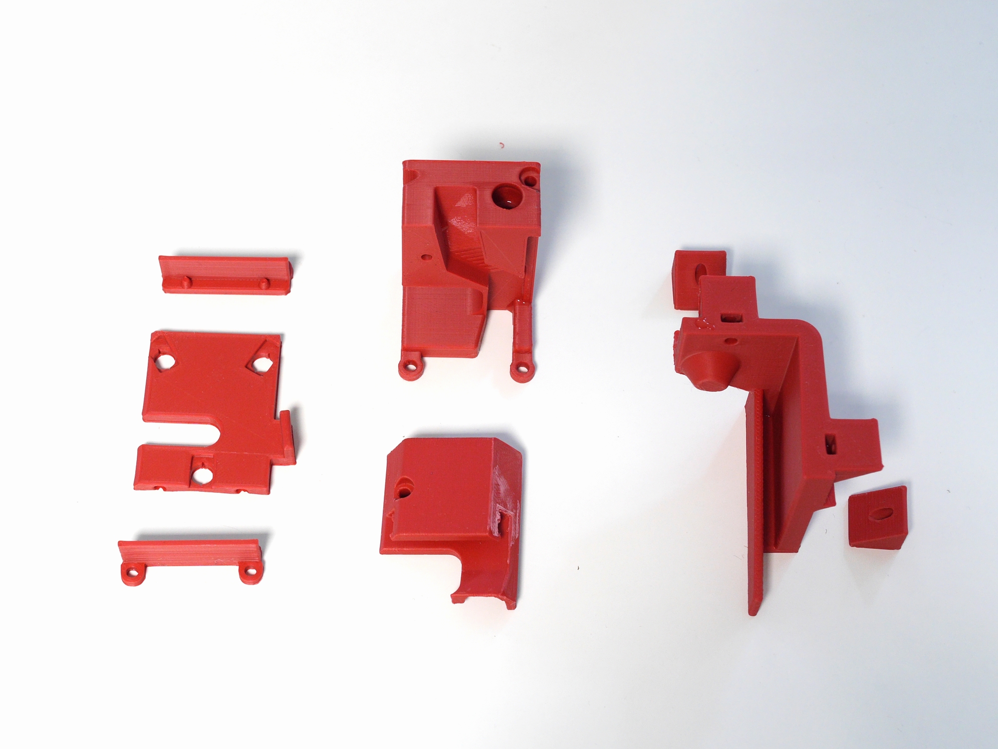
Remove any burrs or elephant feet features. This is especially important for the 6 holes where the magnets will sit.
Surface quality isn't that important, but overall robustness is. It's also a good idea to run a 3mm drill through the holes.
Sand the top surface of the thin angled arm of the dock to remove the layering. This will give the head a smoother and more silent ride when parked and picked up.
Coupling and printhead will be assembled in the next steps.
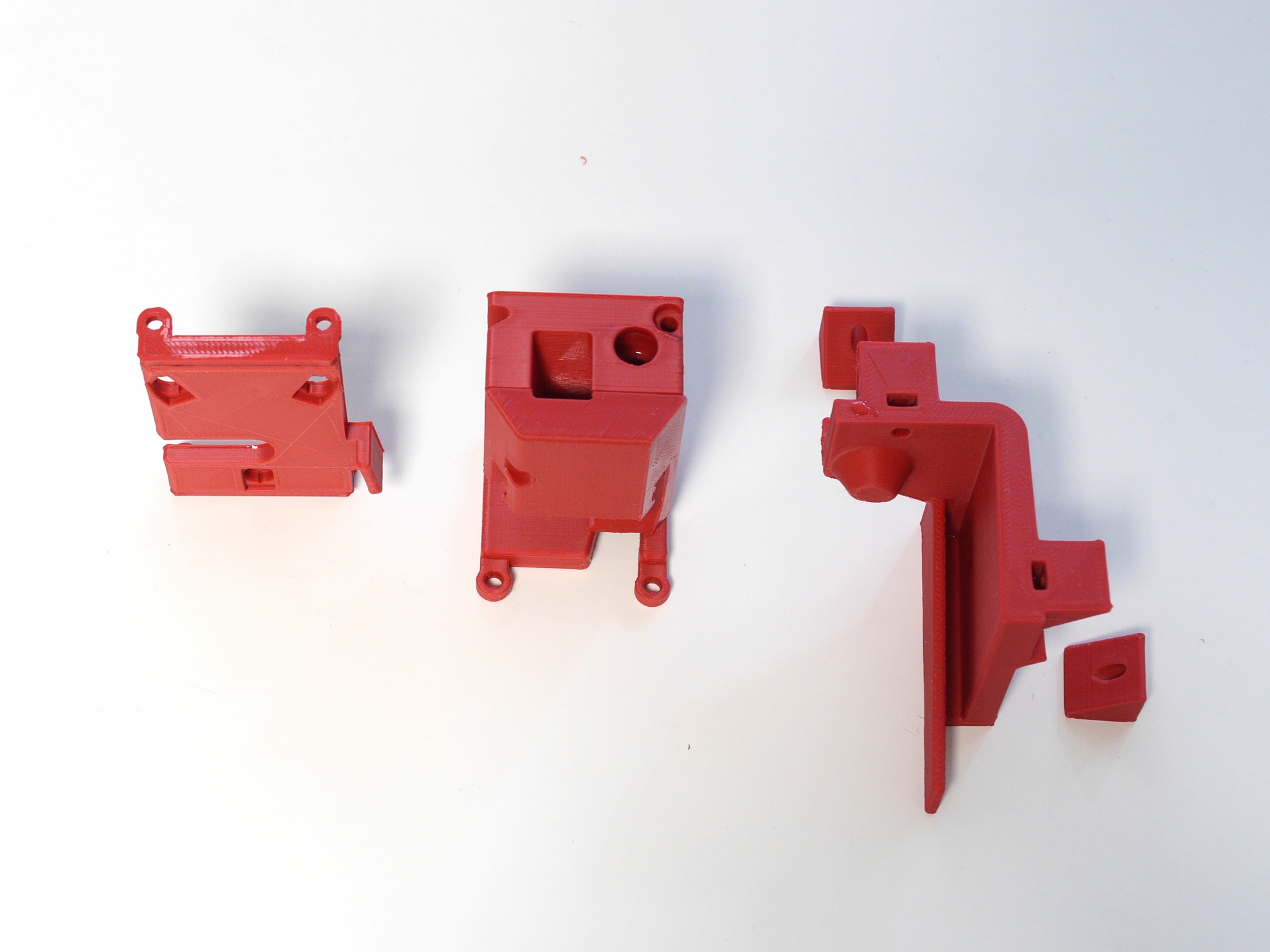
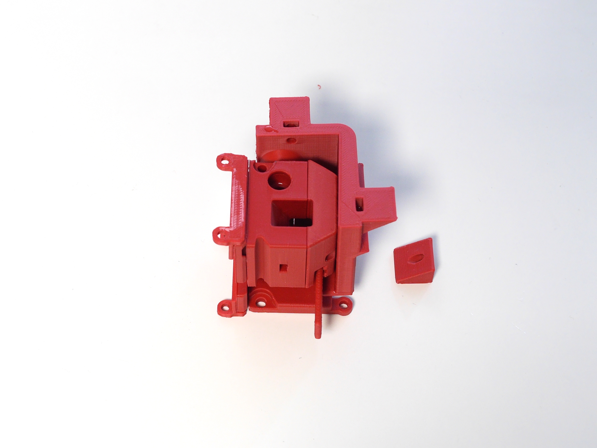
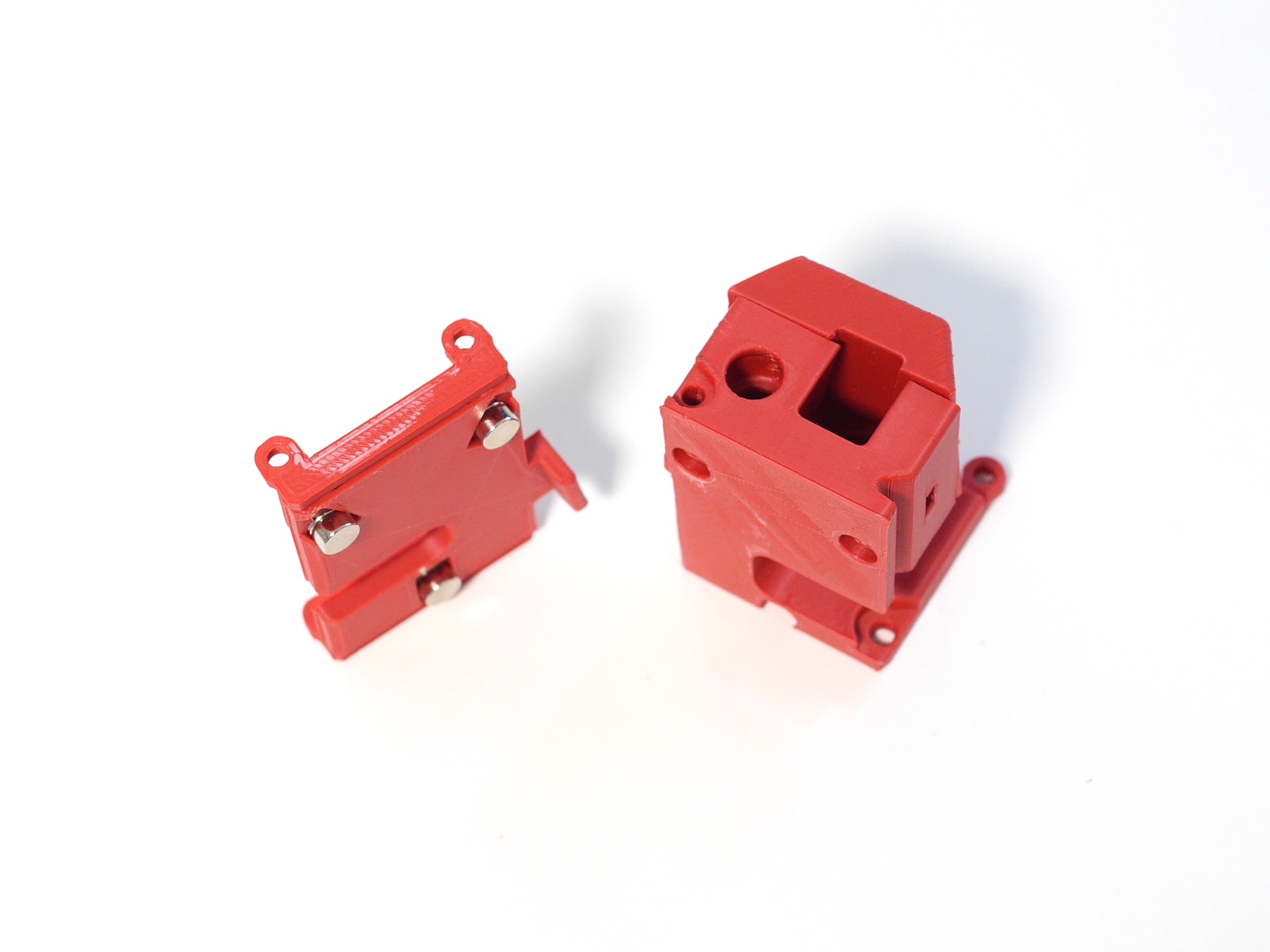
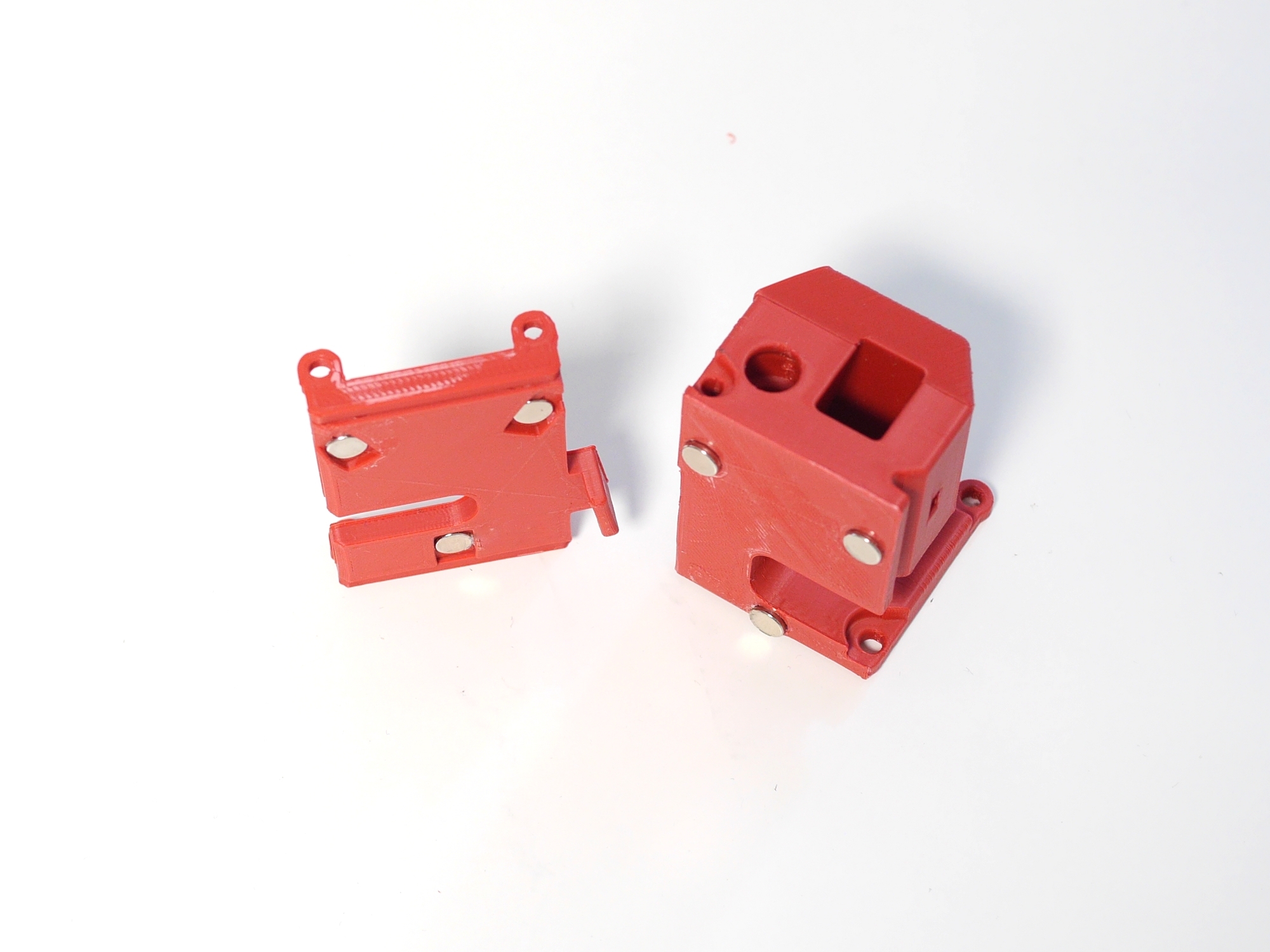
That's how it's supposed to look like at the end.
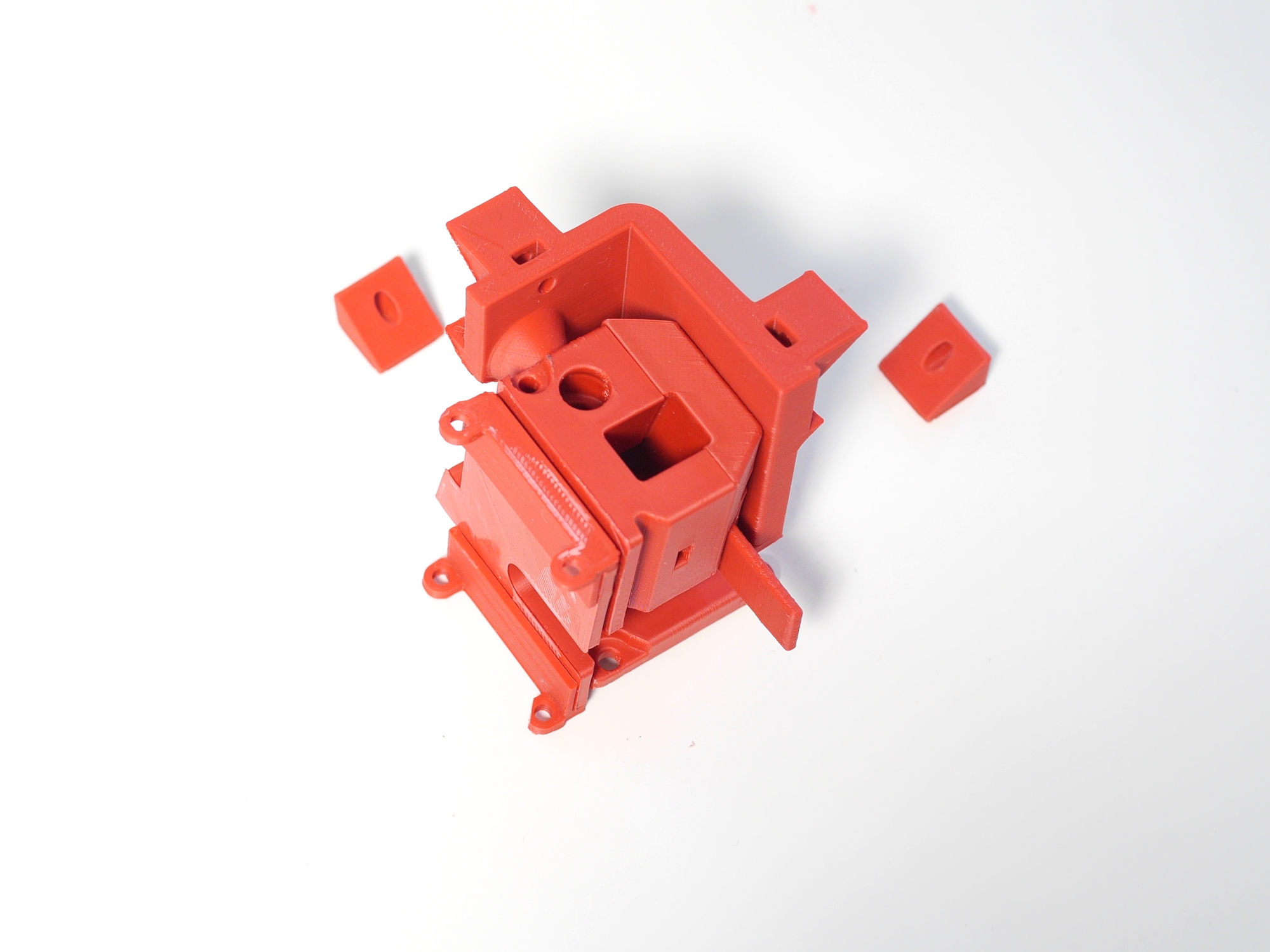
Prepare these two parts and 3 pairs of magnets.
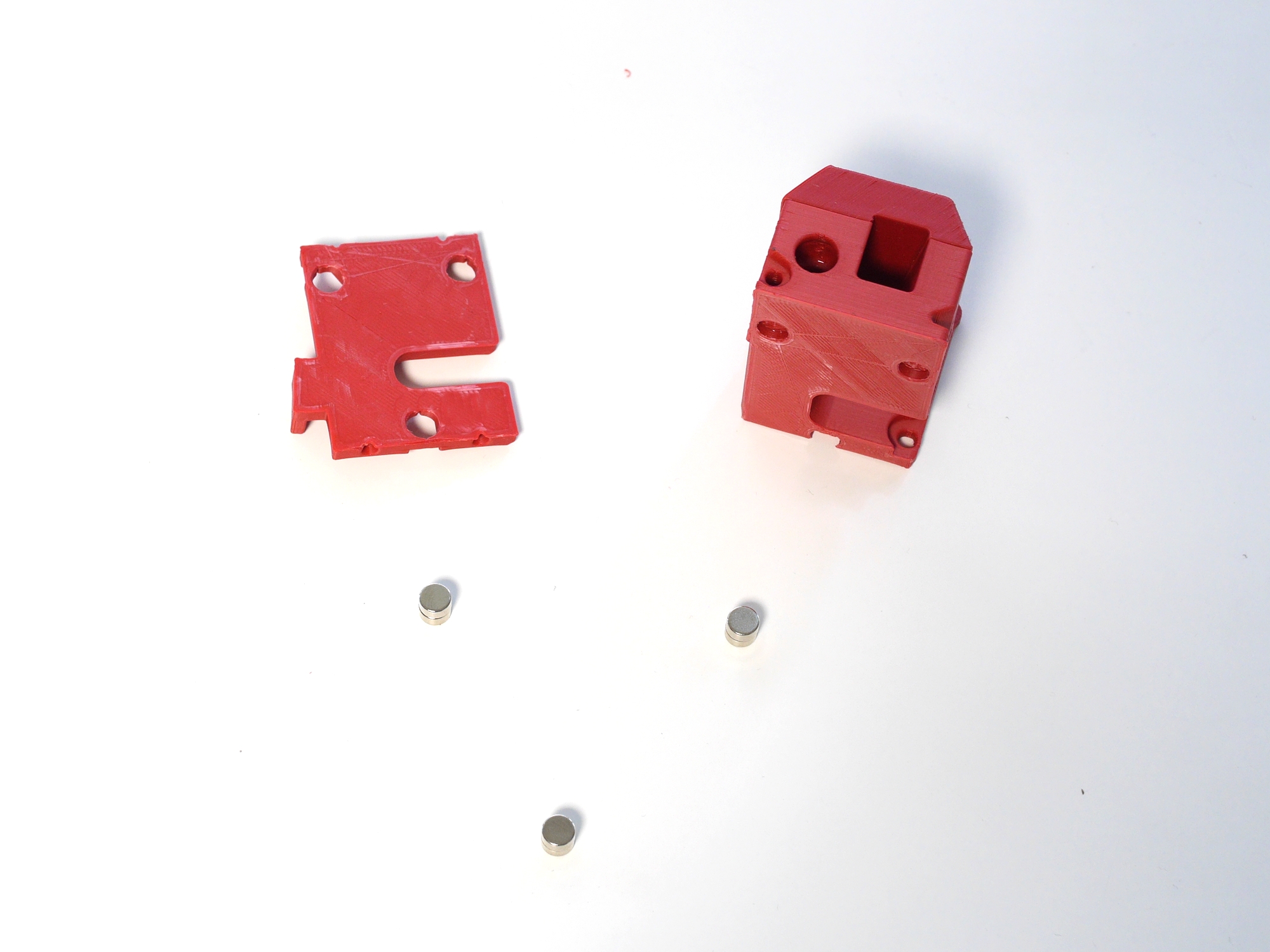
Some additional magnets will help to push them into the holes.
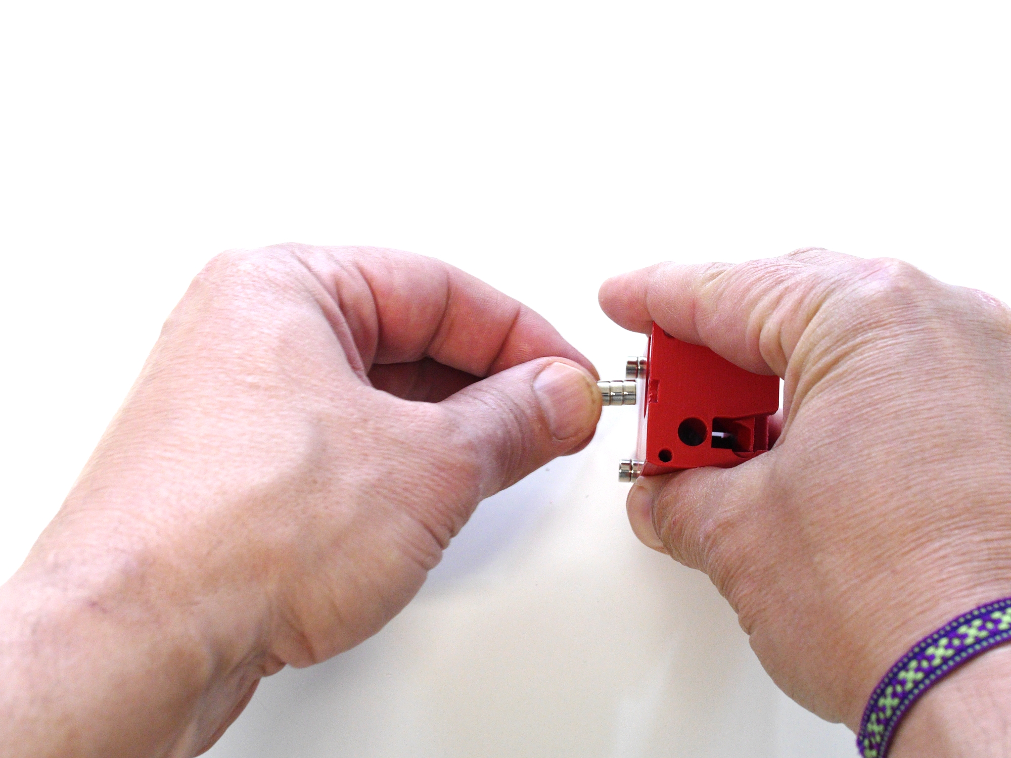
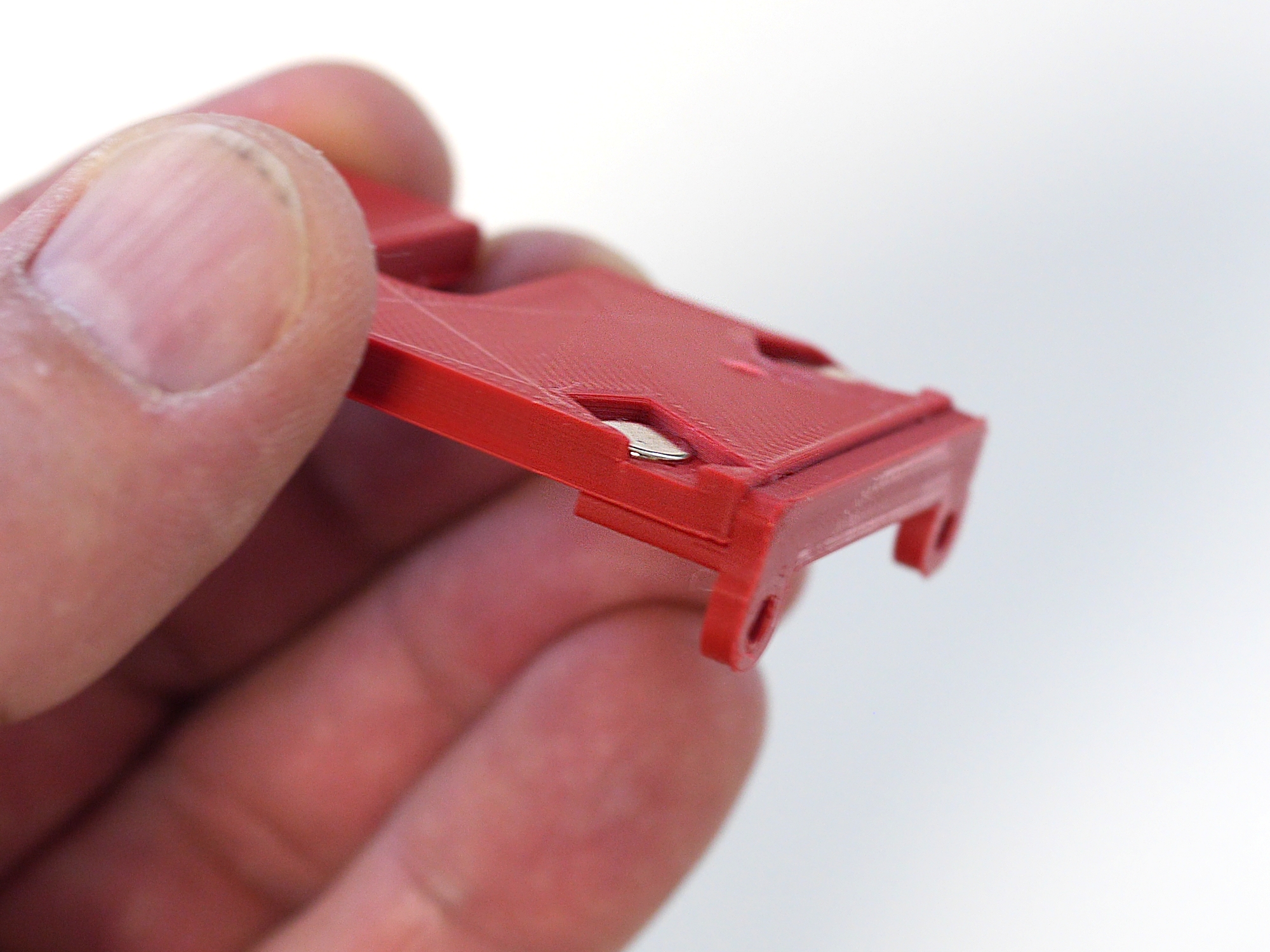
Press firmly against a flat surface.
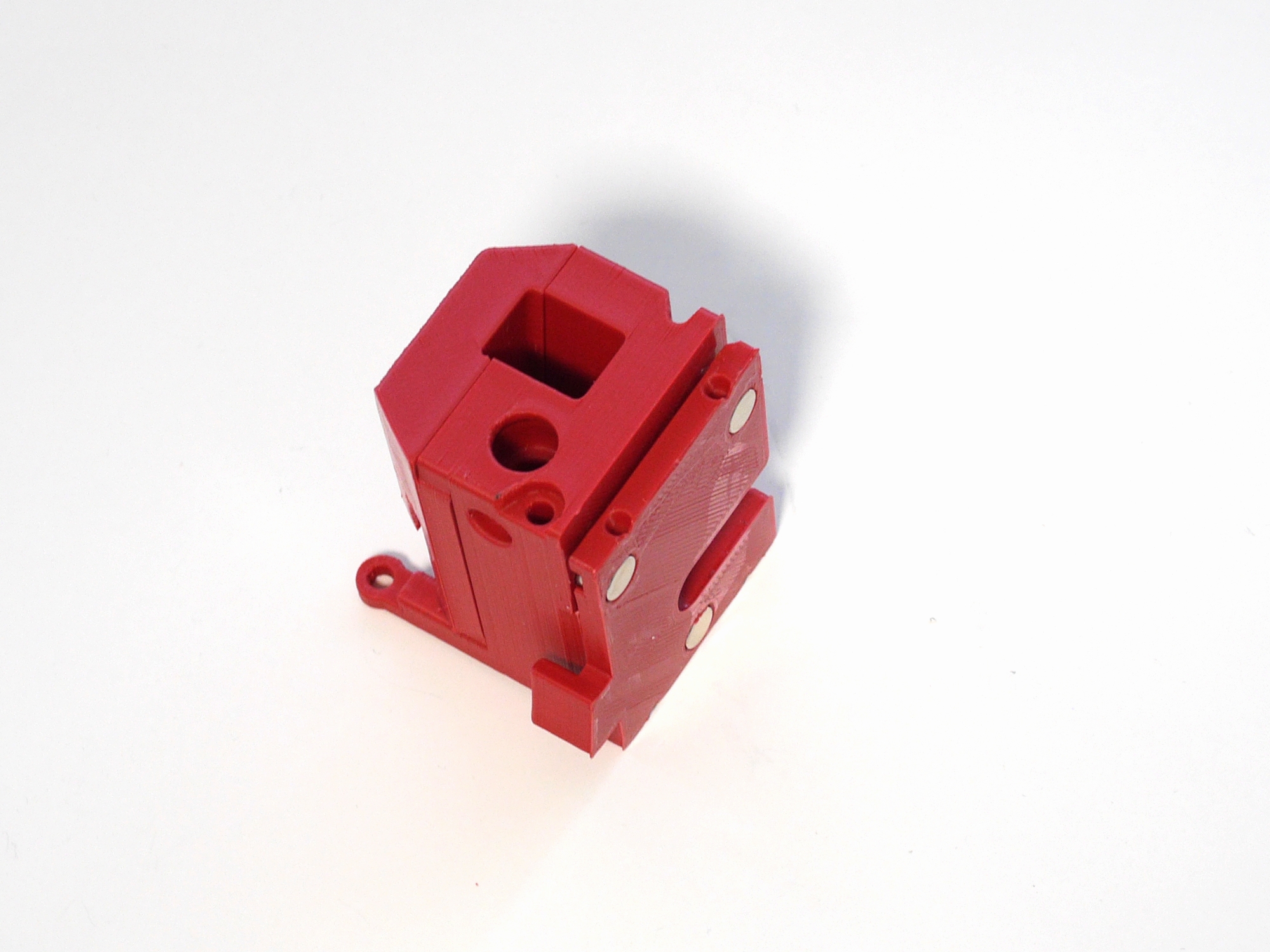
Now it should look like so. Please note: the magnets are protruding approx. 1mm.
Push the coupling part onto the assembly.
Again press firmly.
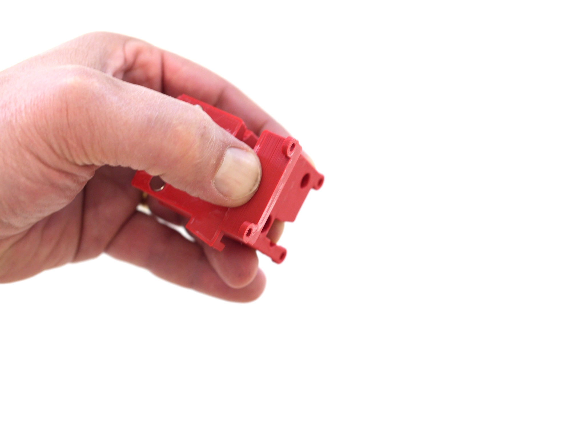
The back surface of the magnets must flush with the back surface of the coupling.
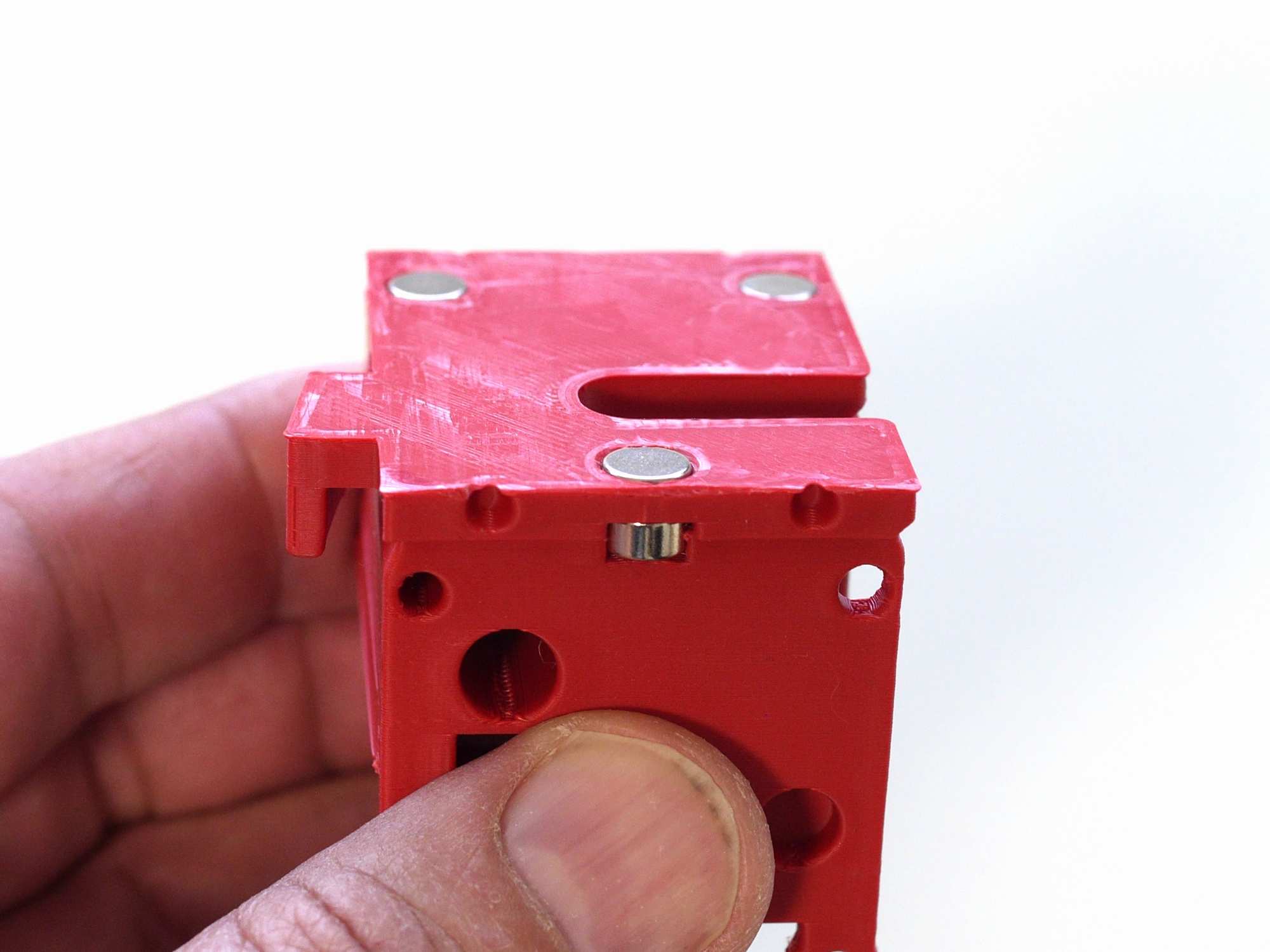
If everything is ok, there's a tiny air gap between both parts.
Next, we're going to glue the top and bottom backet to the coupling.
Apply some glue to the bottom 5 mm of the coupling and the bottom edge.
Push one bracket onto the coupling and hold until the glue settles.
Same for the top part.
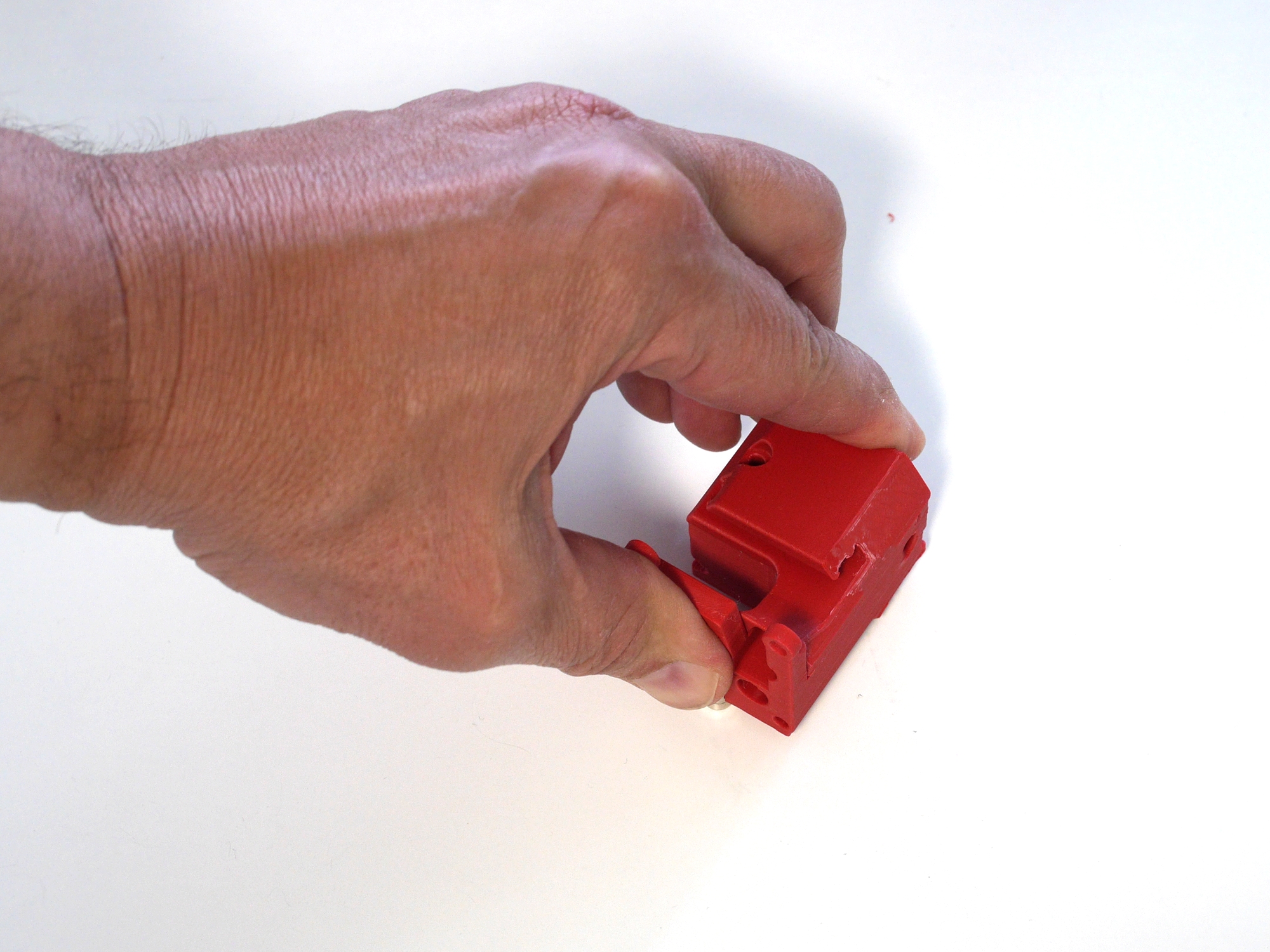
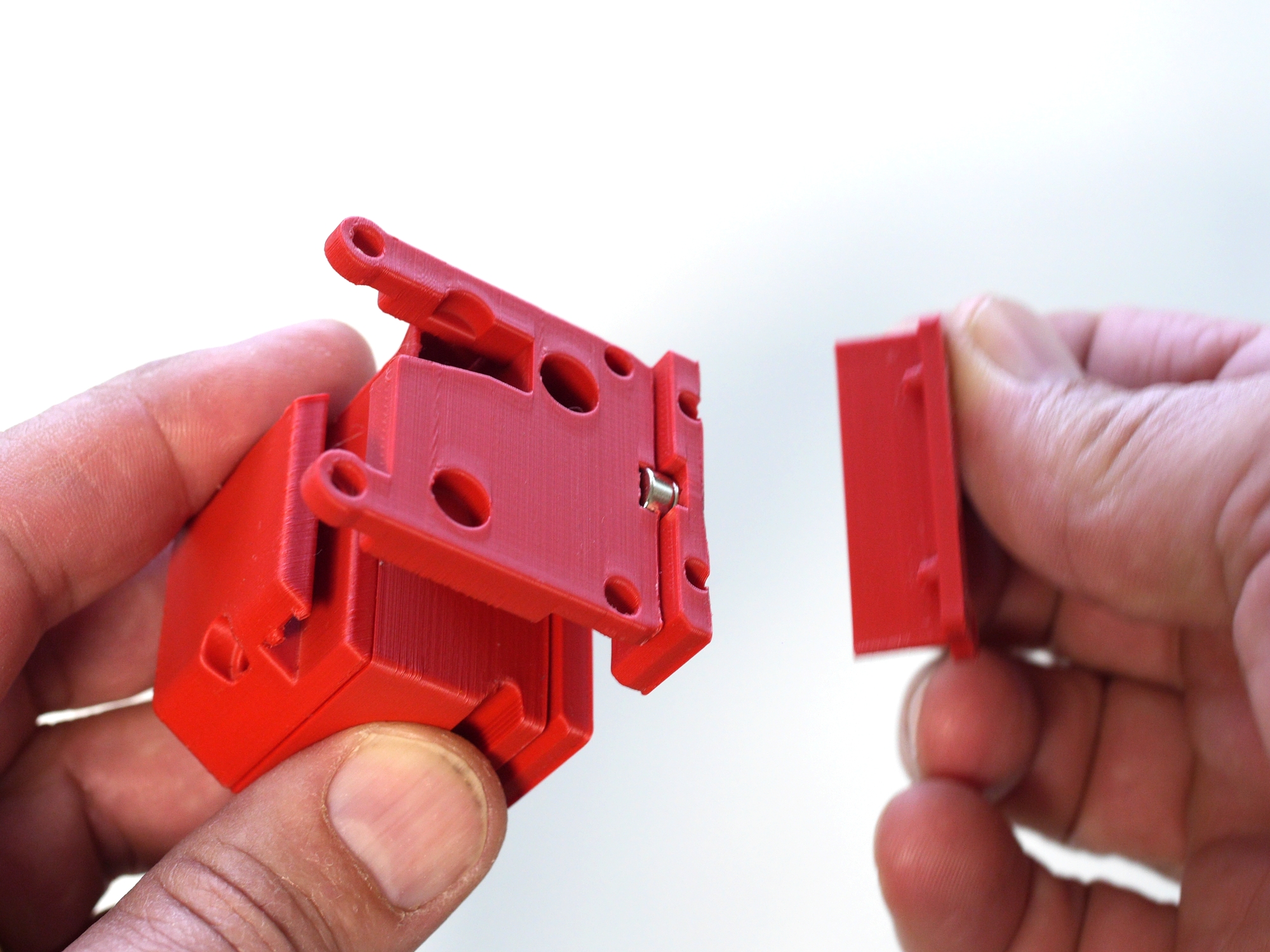
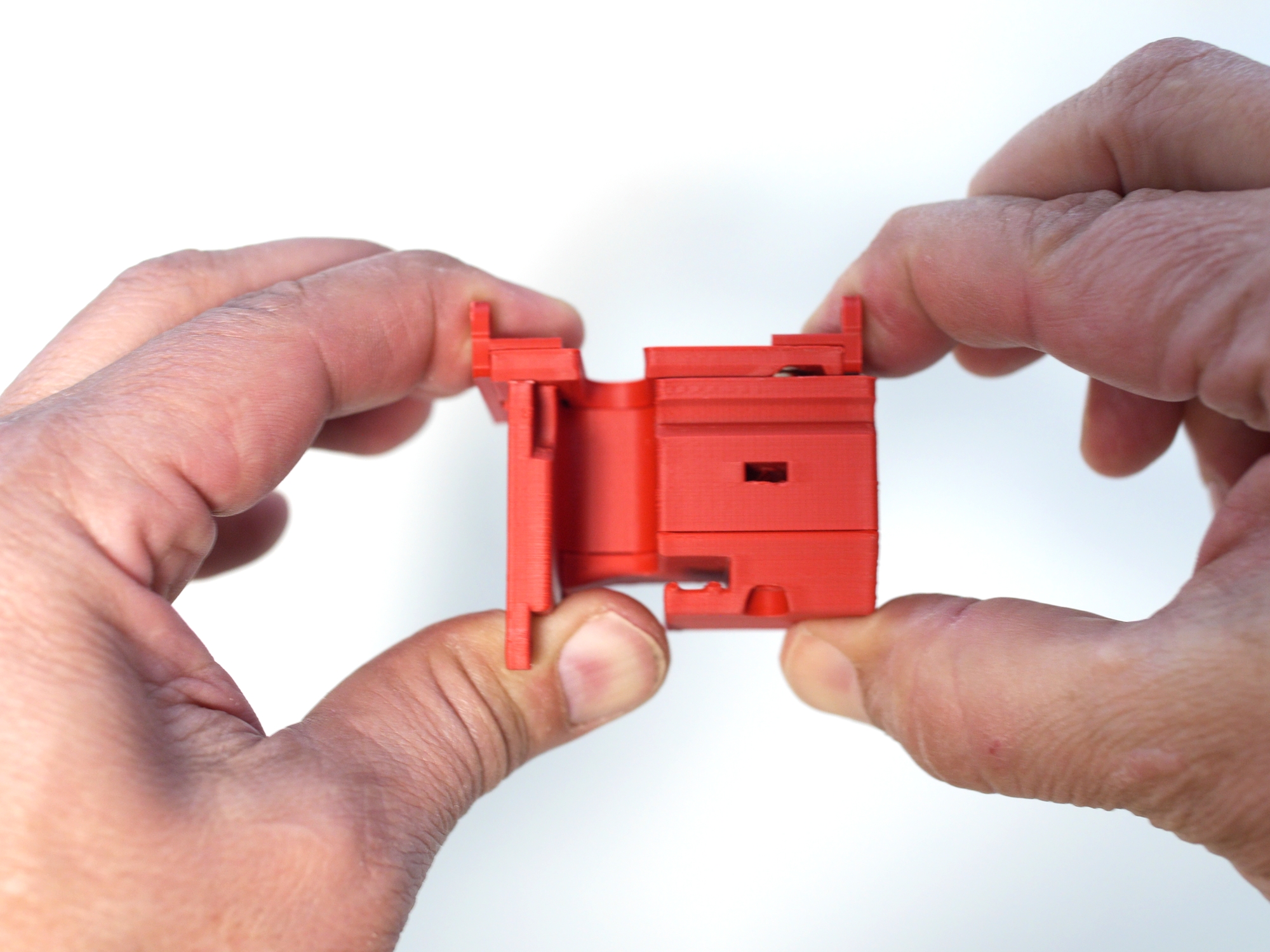
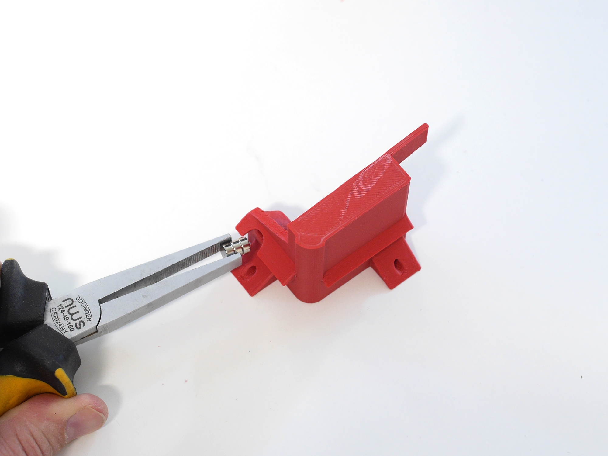
Split both parts. If some magnets stay in the printhead, use some additional magnets oder pliers to pull them out.
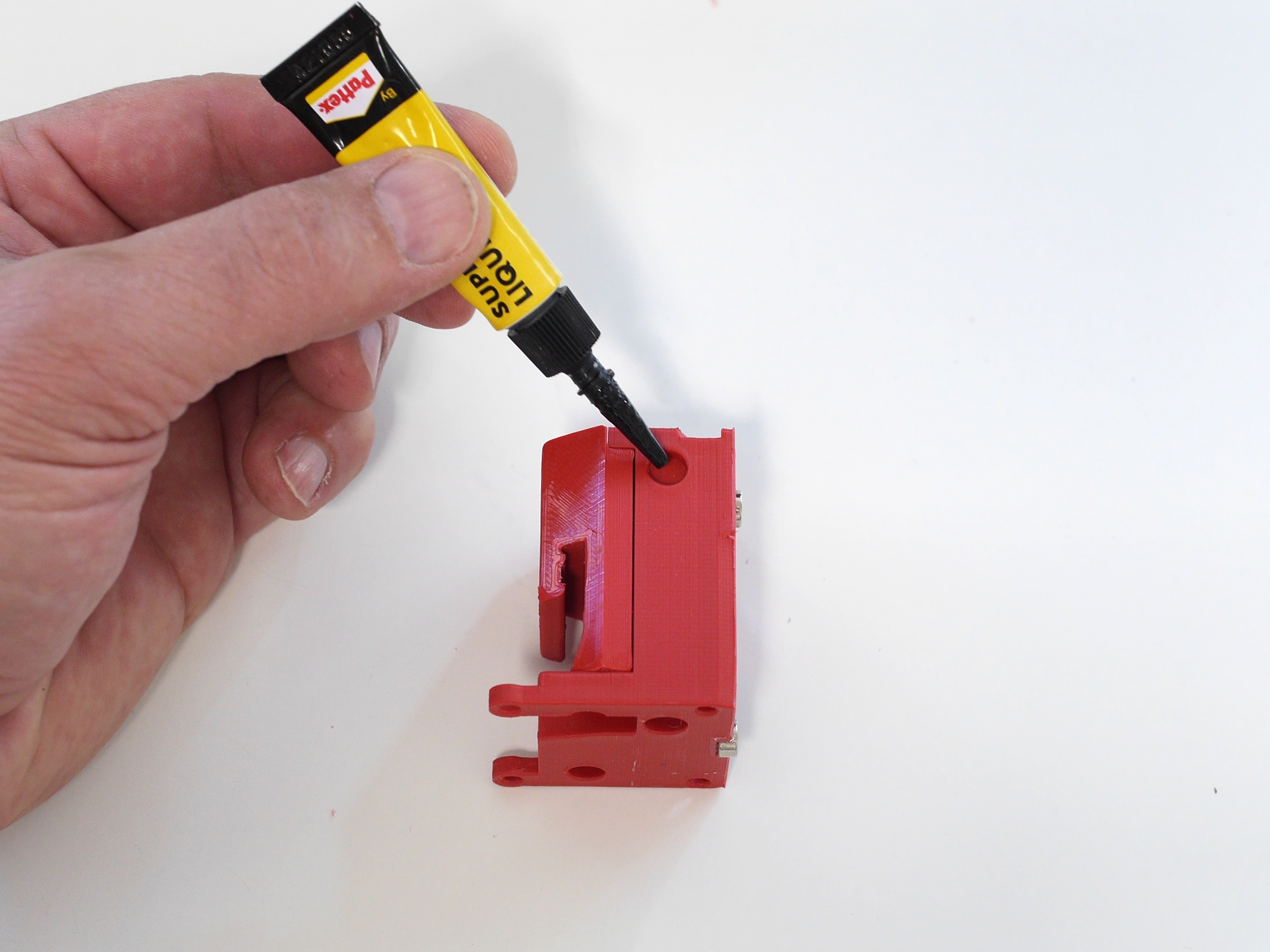
Put a drop (not more!) of glue into each hole. Better to reapply in case than to glue head and coupling together :P
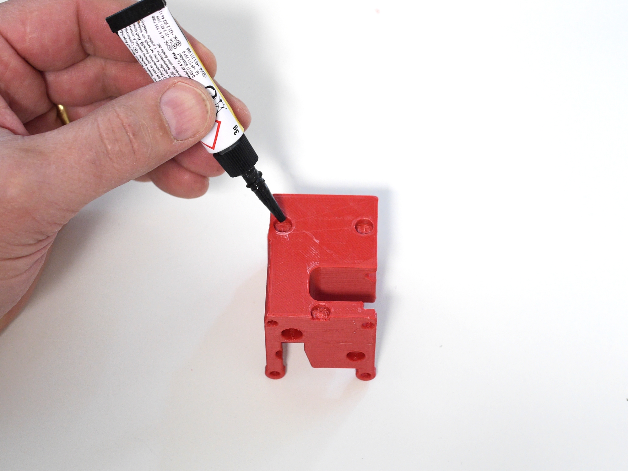
Push both parts together again and press firmly.
The magnetic coupling is ready.
Usually these couplings use 3 ball/V-groove pairs for positioning and additional magnets for holding. We don't have the space to accommodate all this. So we combine the positioning and holding feature.
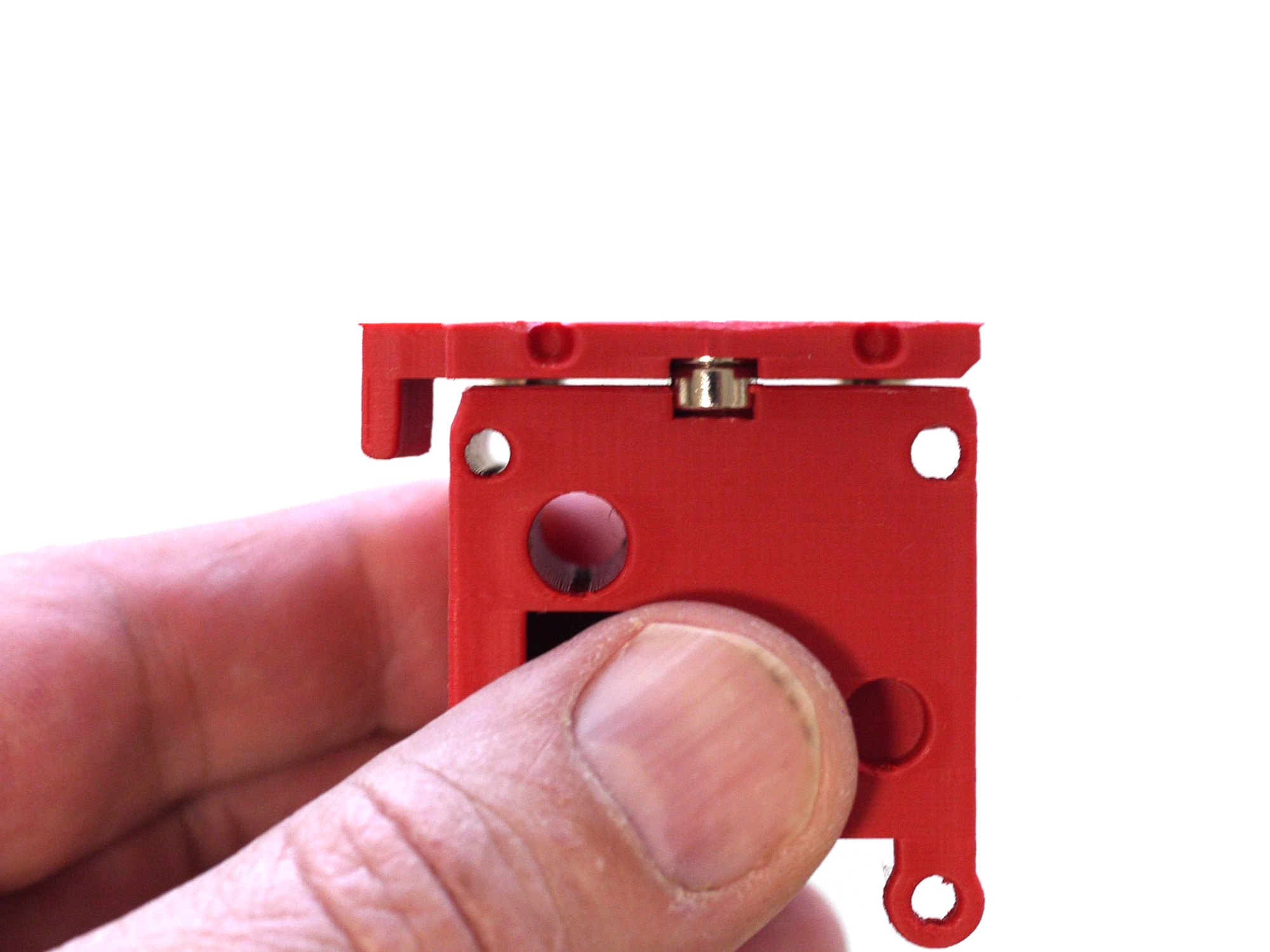
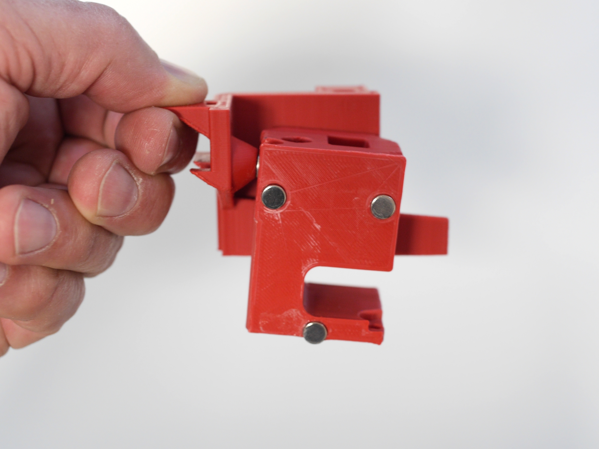
Double check: the magnets are evenly sitting in the pockets, approx. 1mm below the surface.
The rectangular-shaped pockets act as the V-grooves. Make sure, the edges are clean, without any damage and the corresponding magnet cannot move in the direction of the shorter edge.
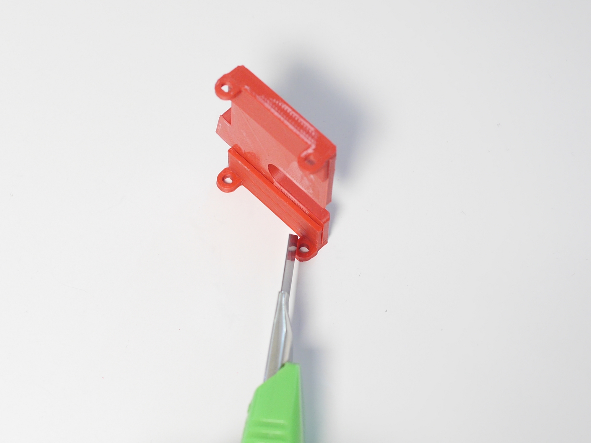
As the TFT spacer of the printhead sits very close to the bottom left eyelet, remove some material.
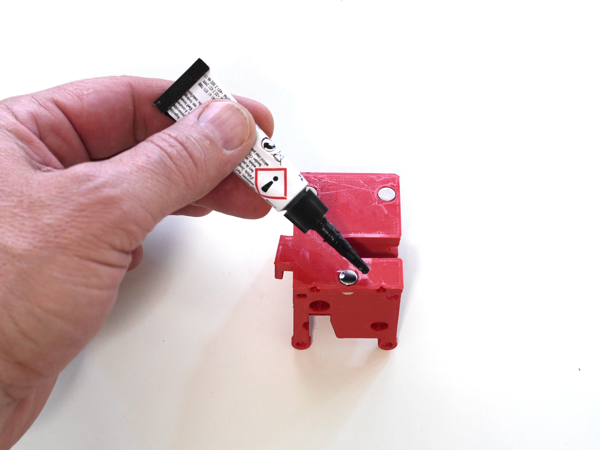
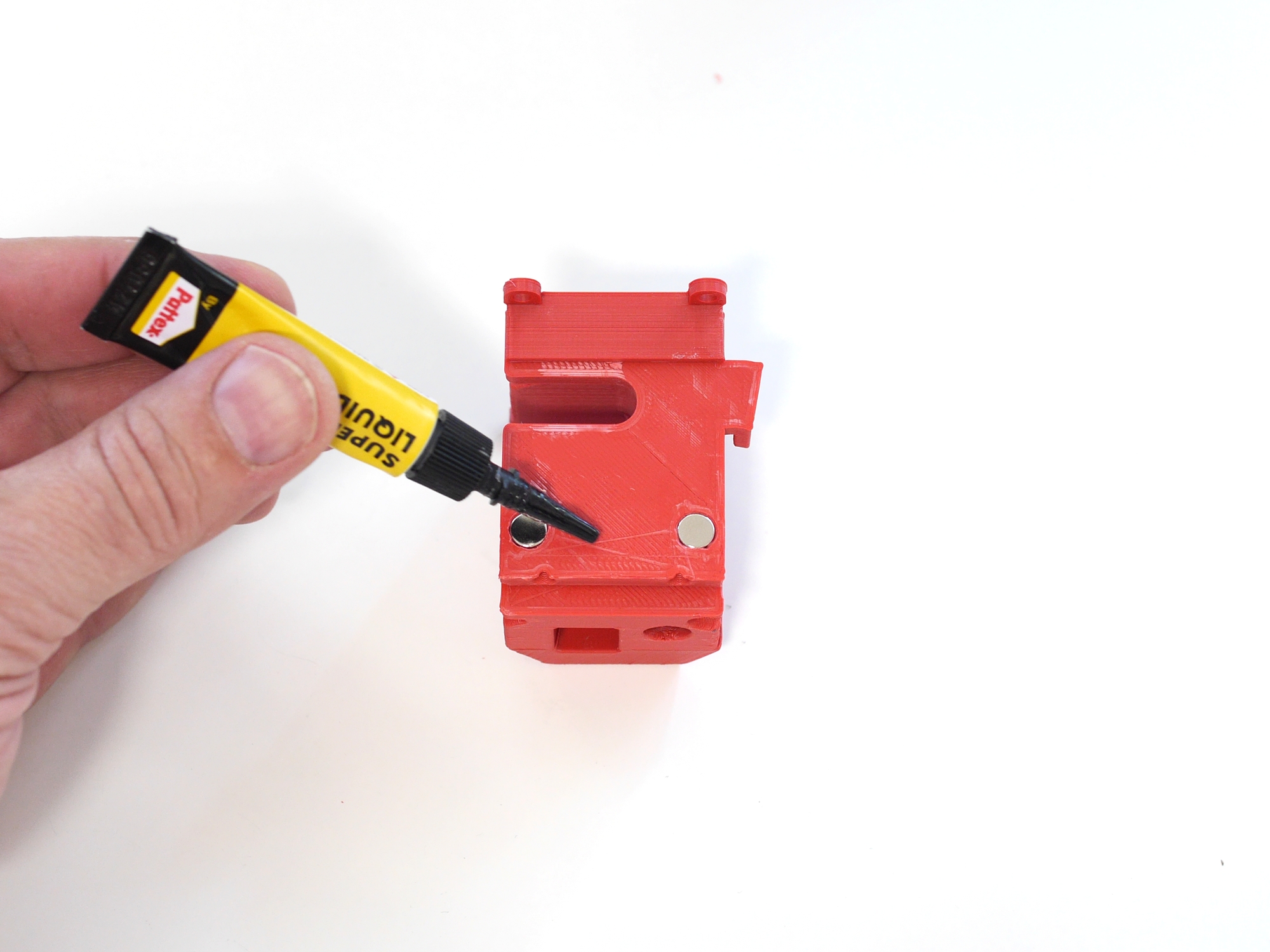
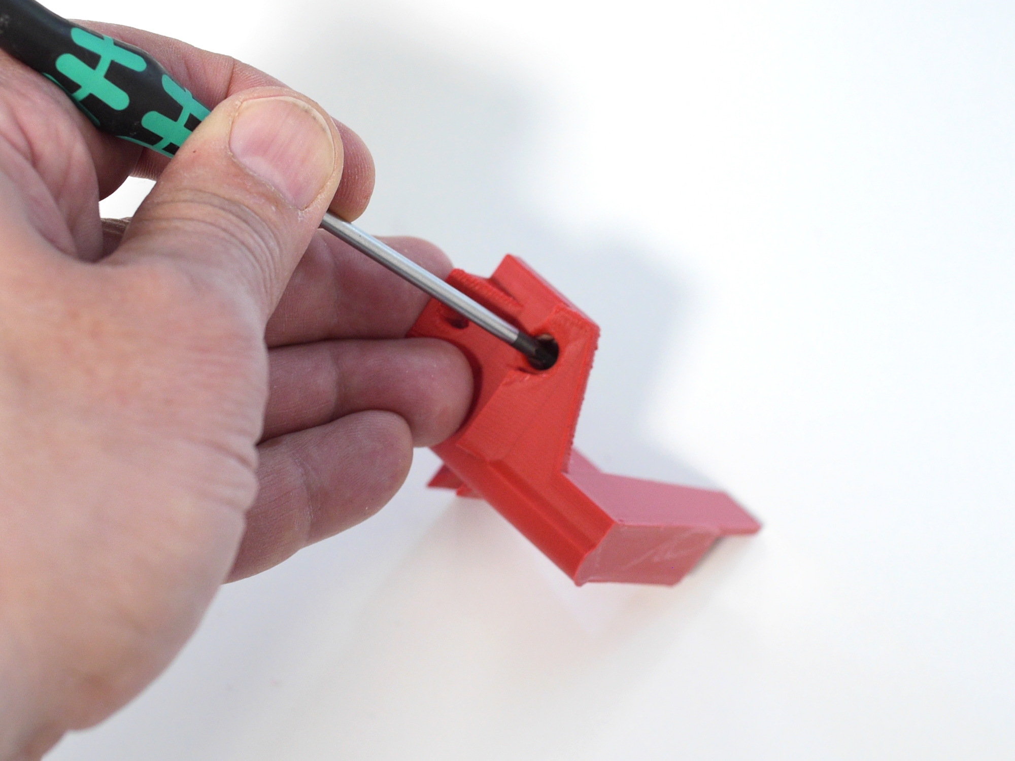
One drop of glue for the magnet which secures the printhead in the dock.
Again use a stack to push the magnet in.
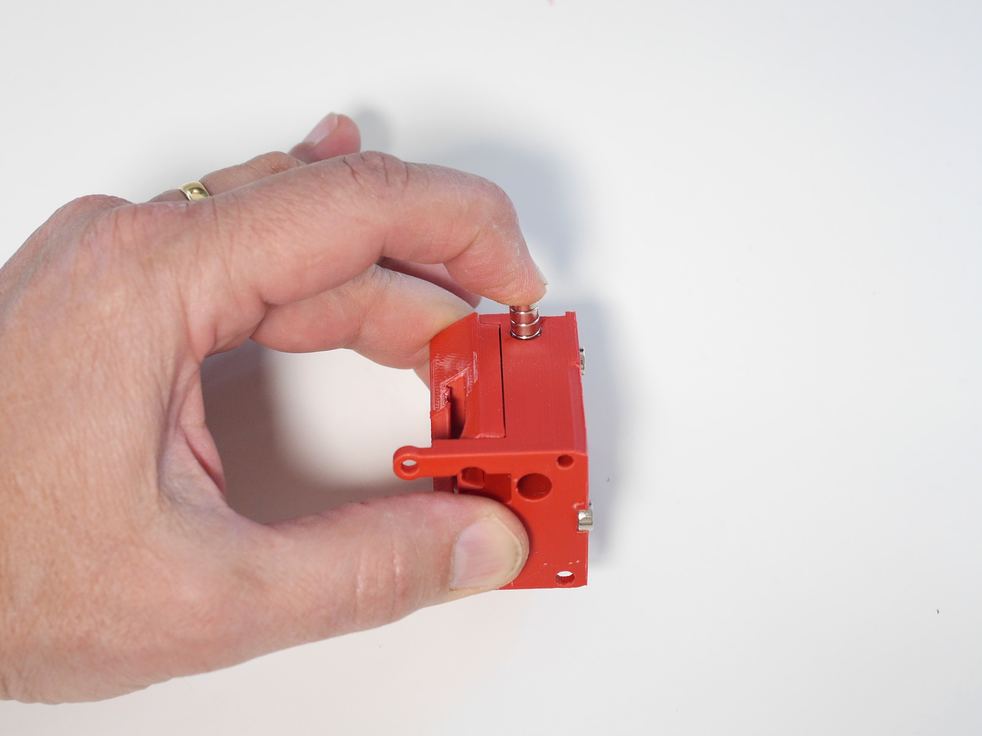
Please double check the orientation of the corresponding magnet! We use no glue here but anyway you won't be able to get it out again, once it has been pushed in.
Push to the very bottom of the hole.
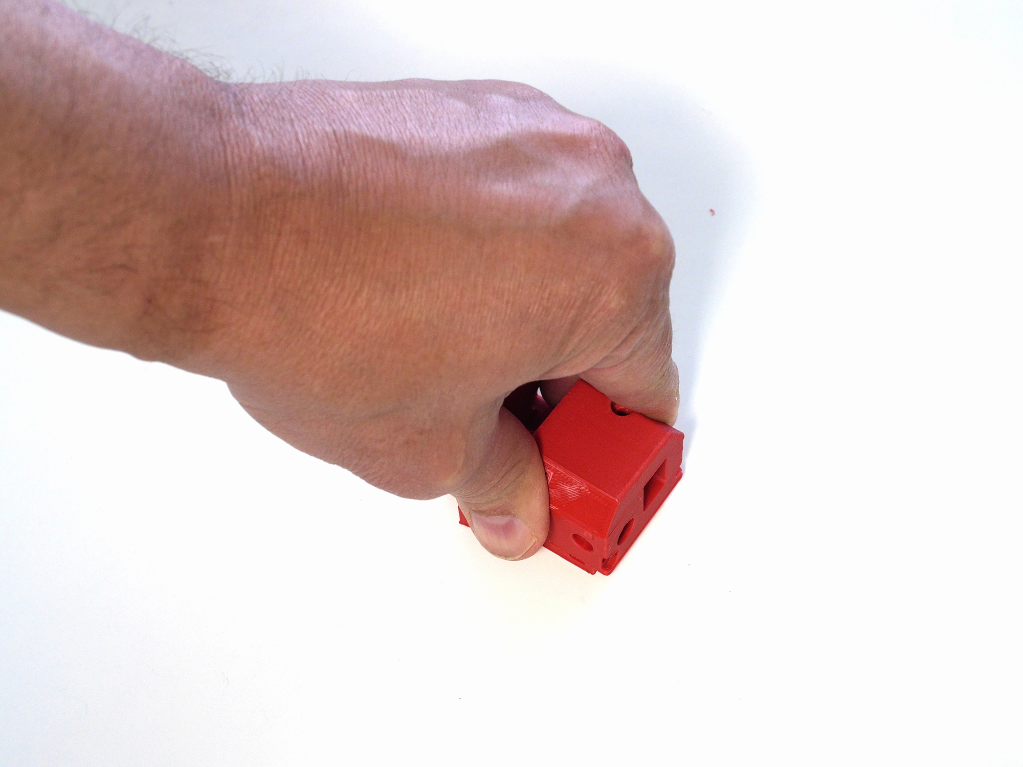
The magnet keeps the parked head in place.
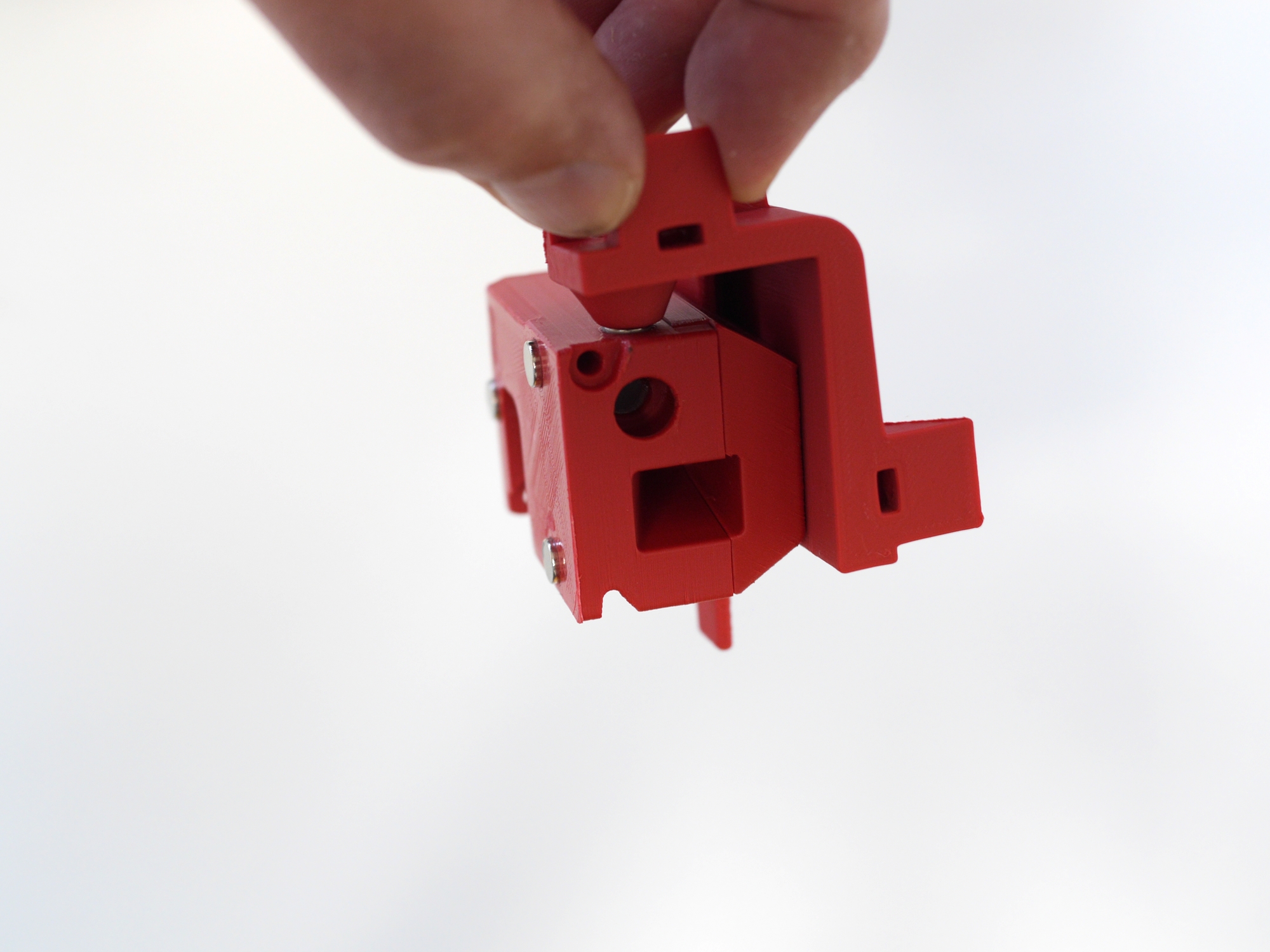
The tilted position is intentionally.
Almost done. Push 2 M3 nuts into the pockets in the dock and one into the pocket on the side of the printhead.
Unscrew the two front thumb screws and mount the coupling to the printhead.
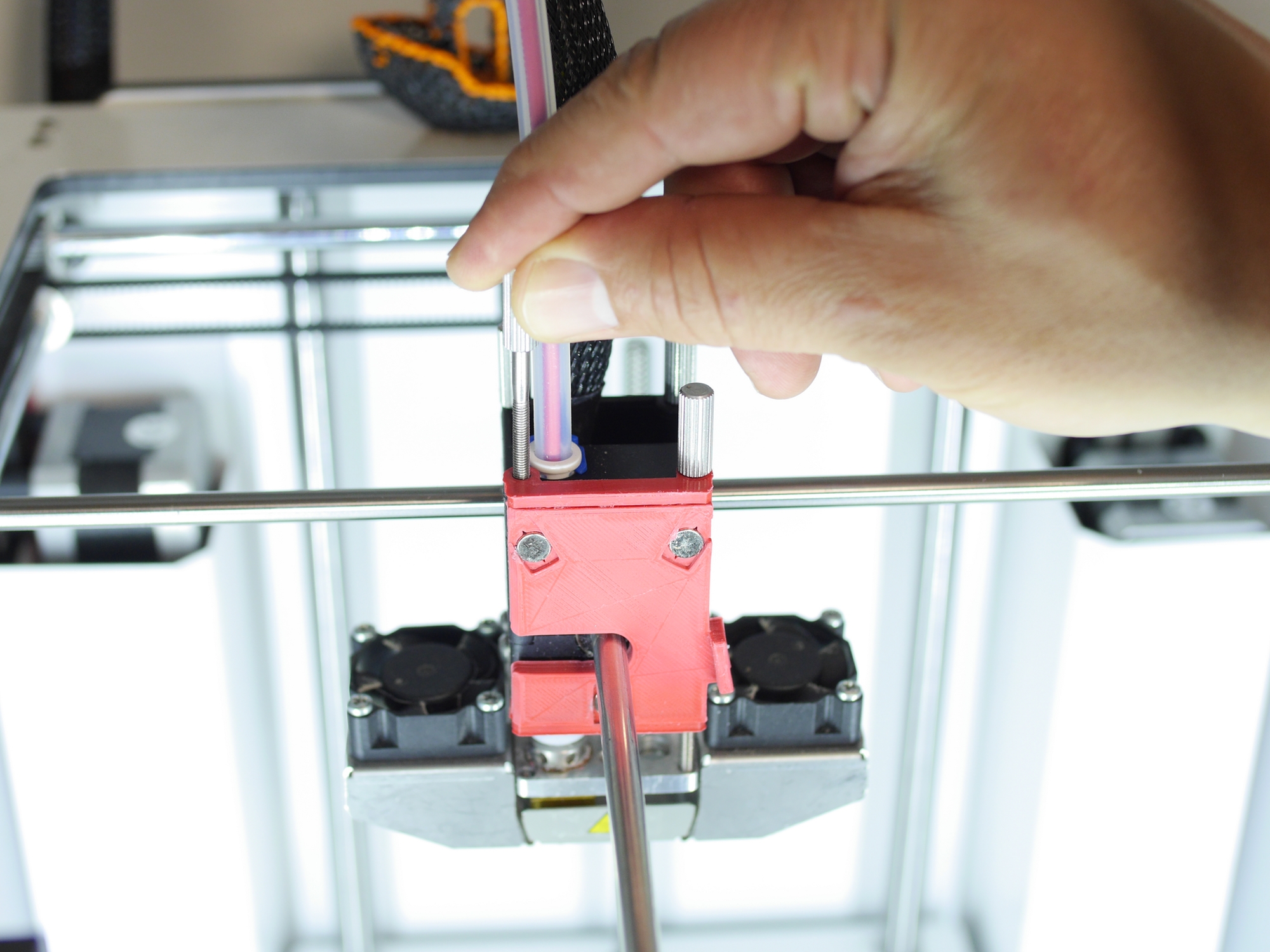
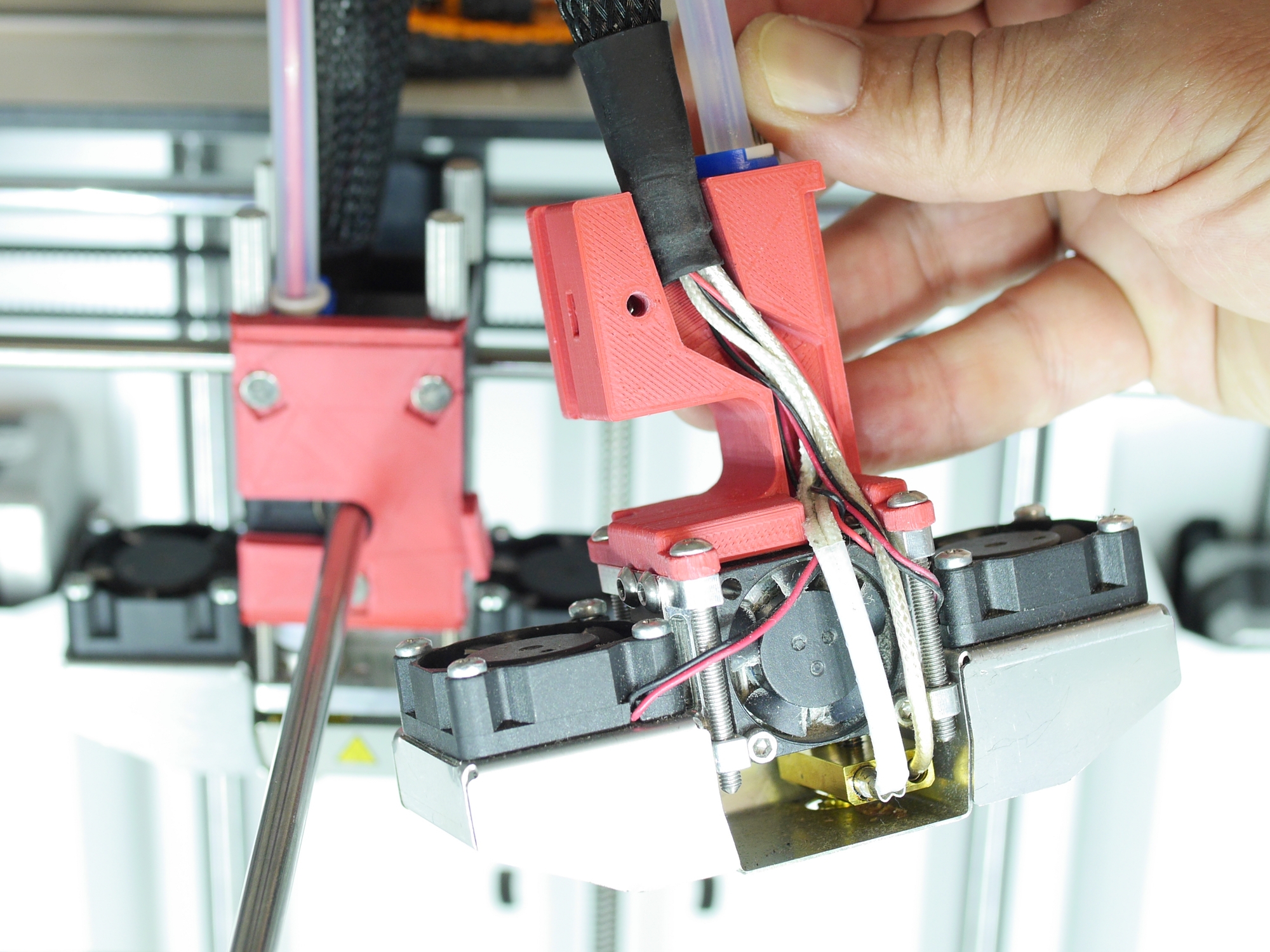
Assemble a mirrored bottom part of a UM2 printhead (nozzle in the right hole). Attach the the printed part with one long thumb screw and three M3x30mm. Arrange the wiring in the cable duct. Mount the bowden tube as usual.
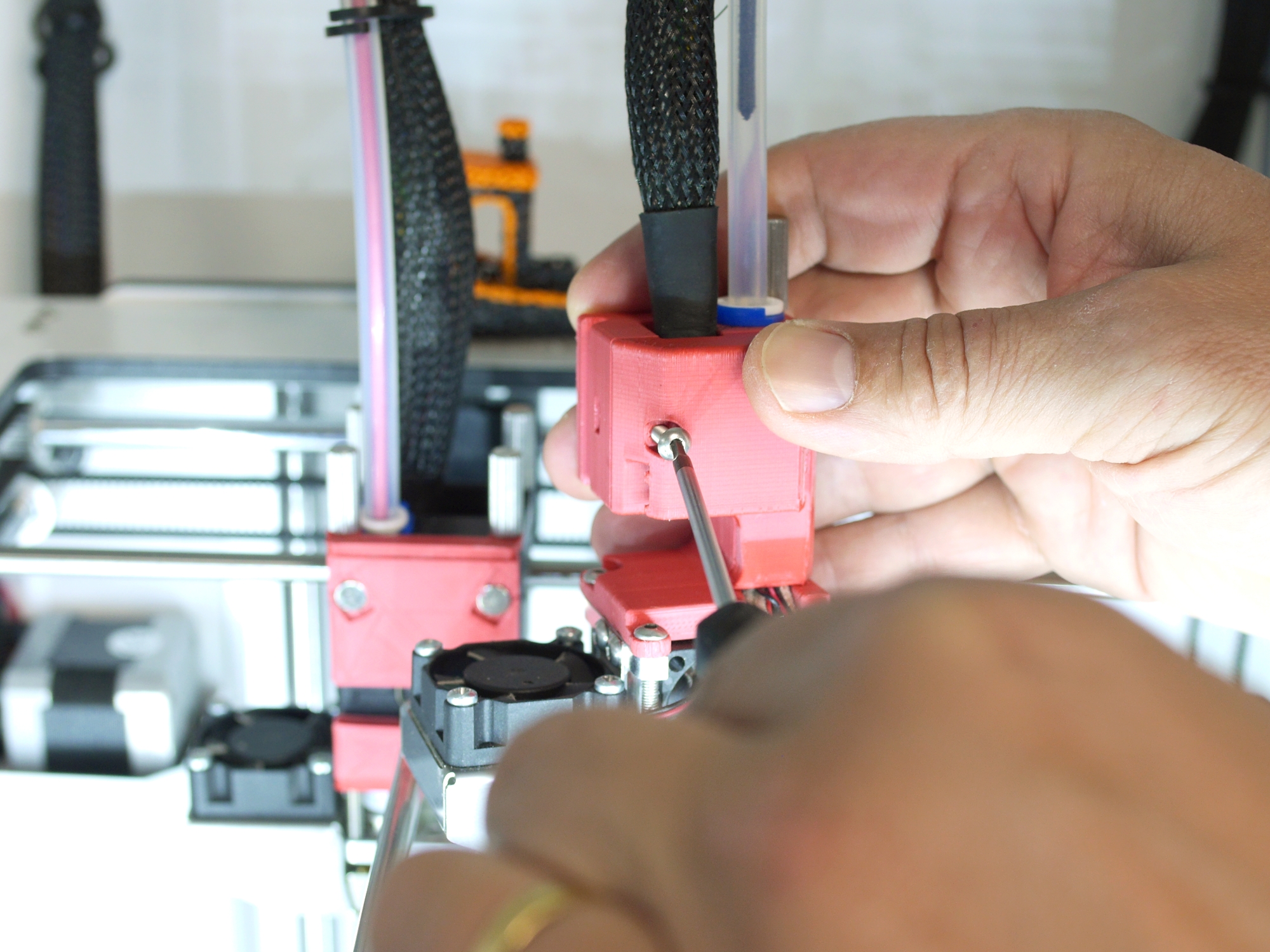
Mount the cover and secure with a M3x16 mm screw.
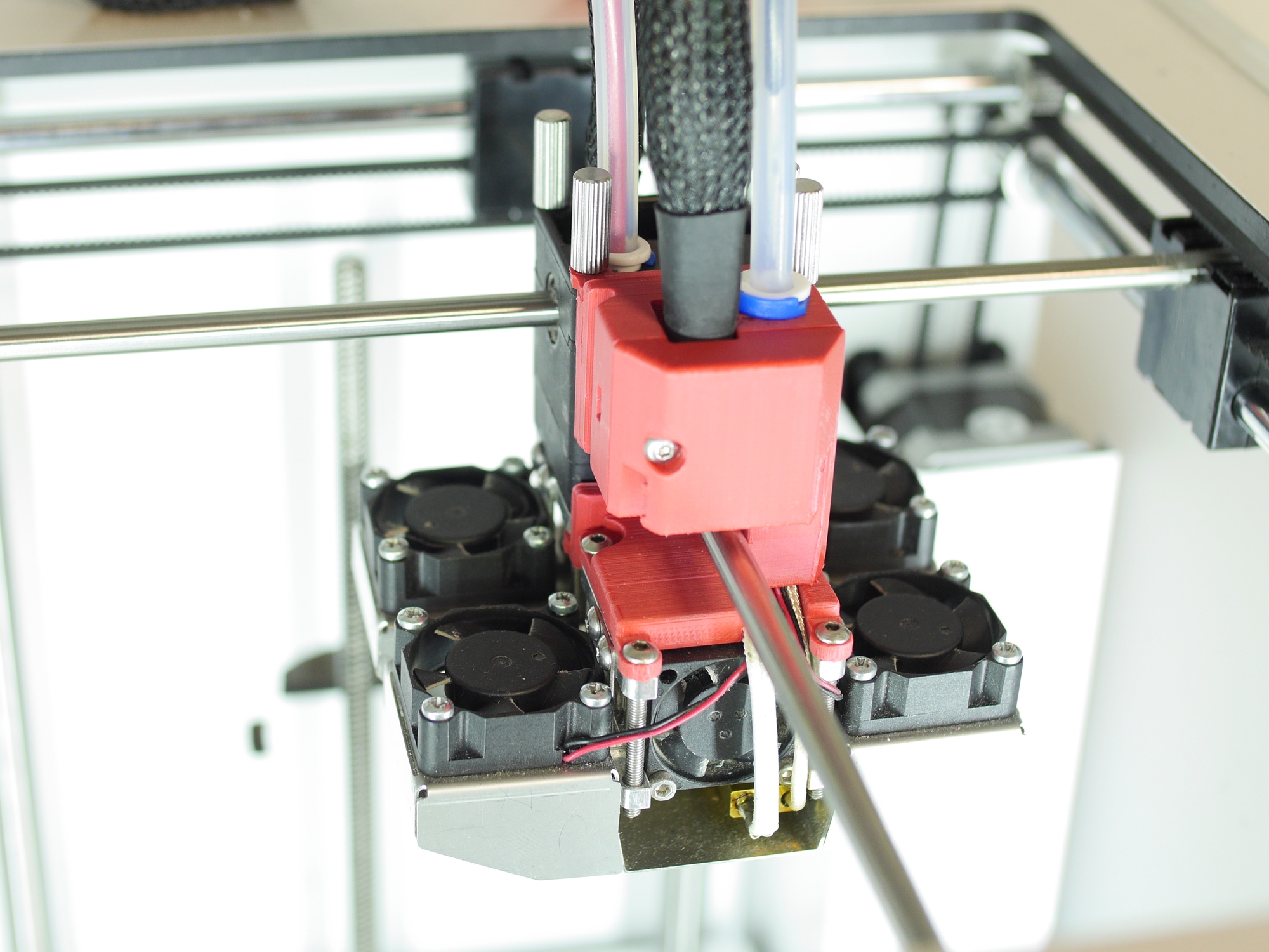
Attach the printhead to the coupling. There shouldn't be any noticeable wiggling.
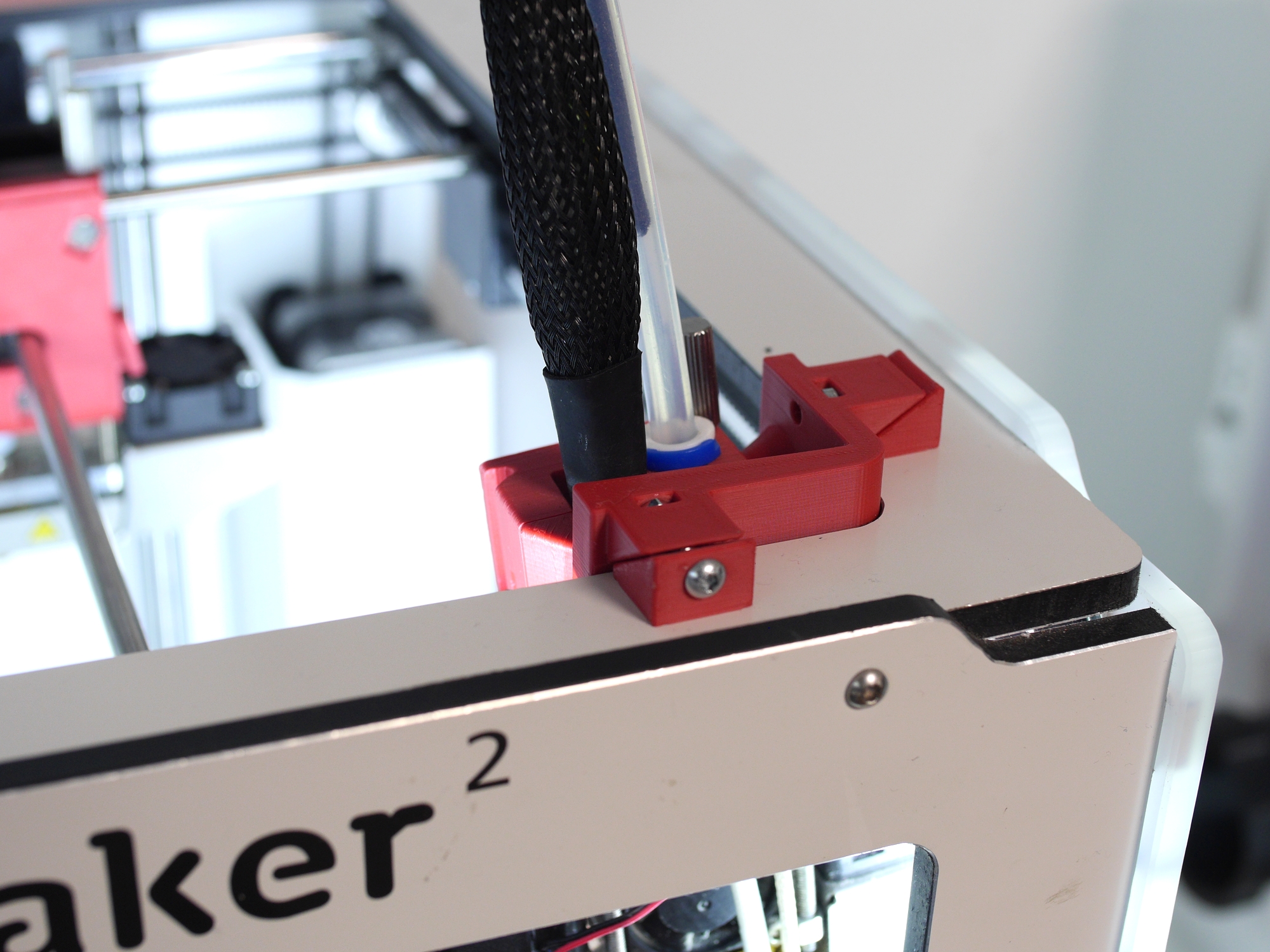
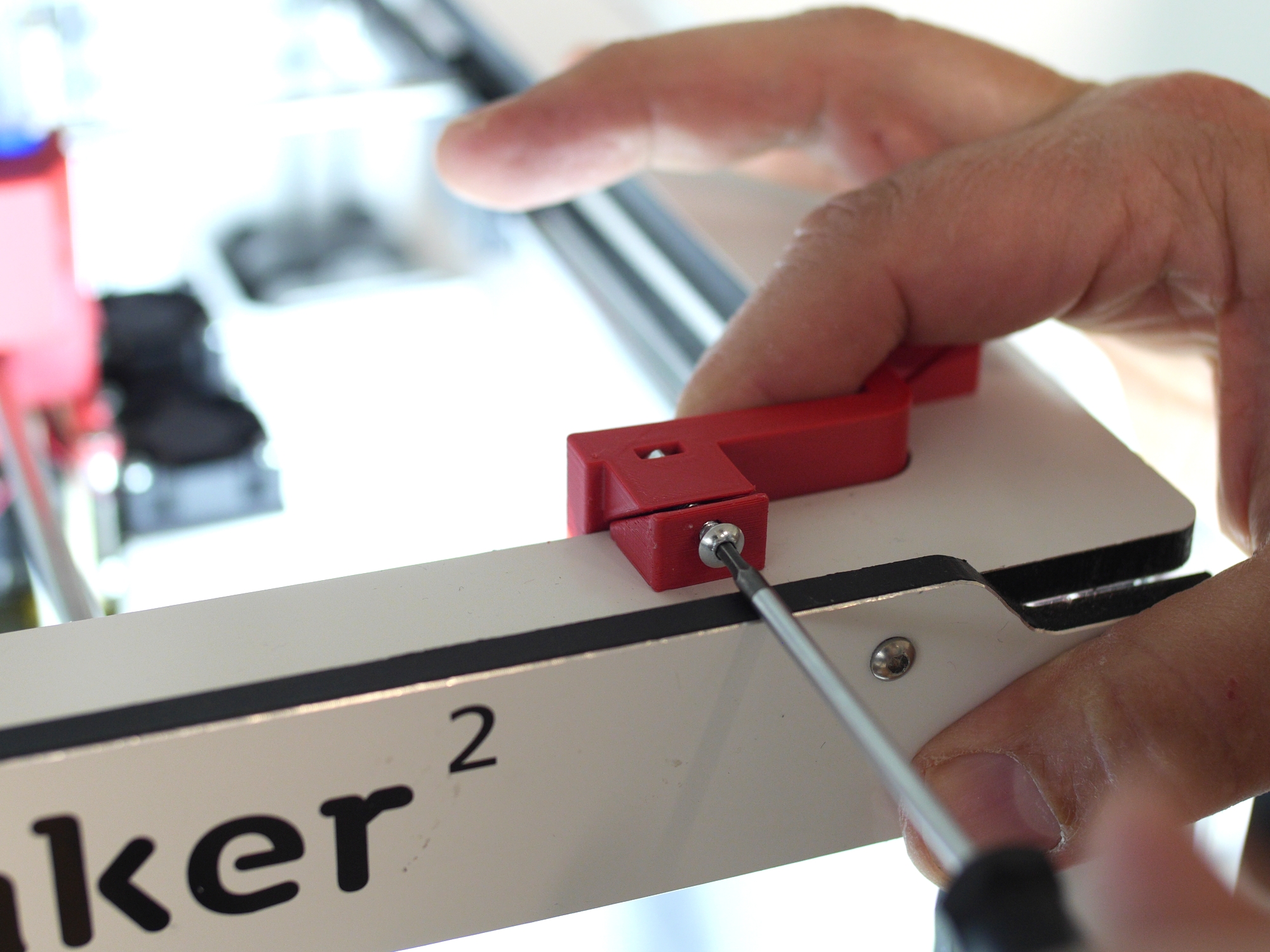
Push the dock onto the front right corner and tighten the wedges with M3x16 mm screws.
IMPORTANT: Do NOT overtighten! Start carefully, check if the dock still moves and in case tighten a little more.
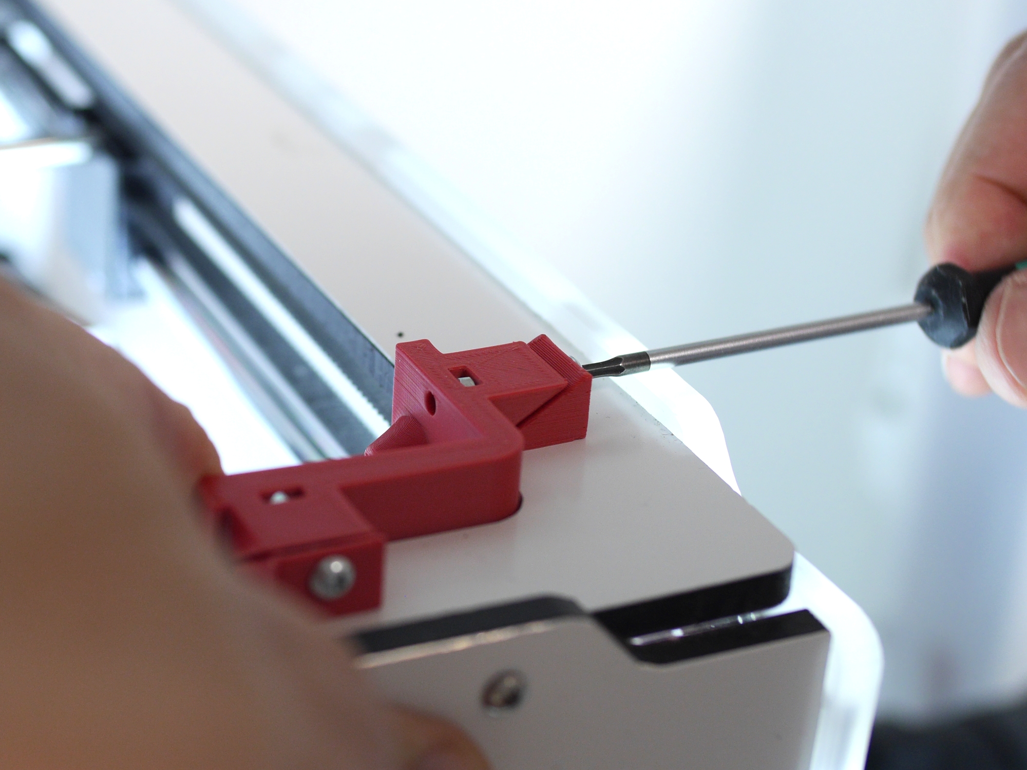
It's a very good option to get the semiflex wedges on Github and print them with some semiflex material. They provide even better clamping without any risk of overtightening.
Same goes for the other wedge.
Congratulations!